BPX-8600 and SES-Based PNNI Node
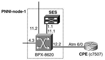
| The BPX-8600-based PNNI node is the first one that is brought up. The PNNI node is formed by a BPX-8600 switch controlled by a SES PNNI controller. Figure 10-5 shows the details of this PNNI node. Figure 10-5. BPX-8600 SES-Based PNNI Node
We will analyze this scenario in two steps. First you will bring up the PNNI node. Then in the next section, you will configure its interfaces that interconnect this node to other PNNI nodes. PNNI Node Bringup: BPX + SESTo bring up the multiservice switching PNNI node, you need to start VSI communication between the controlled switch and the PNNI controller. You up the physical and ATM layers in the BPX-8600 control interface using the command uptrk to up a trunk between the BPX-8600 and the SES PNNI controller. You use 11.1 in the BPX-8600 as the control interface. It is important that the protocol for the control interface be run on the BCC controller card and not in the BXM card. This is achieved with the following trunk setting using the command cnftrk: Protocol By The Card: No The statistical reserve protects VSI protocol traffic. It can be changed with the command cnftrk. The default value is appropriate. In the SES, the control interface is always up, so you do not need to modify it. You add the SES as shelf type AAL/5. See Example 10-1. Example 10-1. Adding a Service Expansion Controller Shelfb8620-5a TN Cisco BPX 8620 9.3.4L Feb. 19 2002 20:12 GMT BPX 8620 Interface Shelf Information Trunk Name Type Part Id Ctrl Id Control_VC Alarm VPI VCIRange 11.1 SES-3a AAL/5 - - - - OK Last Command: addshelf 11.1 x Shelf has been added Next Command: This effectively establishes LMI communication between the BPX and the SES using VPI/VCI 3/31. It also creates the PVC 3/8 for IP Relay traffic. You define a partition in the control interface using the command cnfrsrc. VSI will use this partition to create connections terminating in the SES controller. In this case, partition 1 is configured. It is important not to include VPI 3 in the partition's VPI range because this VPI is being used by LMI and IP Relay. The total bandwidth managed by VSI in the control interface is the total physical bandwidth minus the statistical reserve. You now assign SCT 3 to the partition. SCT 3 includes MPLS and PNNI service types, as shown in Example 10-2. PNNI service types (also called ATM Forum service types) have policing off in SCT 3. Example 10-2. Assigning a Service Class Template to a Portb8620-5a TN Cisco BPX 8620 9.3.4L Feb. 19 2002 20:15 GMT Trunk: 11.1 Service Class Template ID: 3 VSI Partitions : channels bw vpi Part E/D min max min max start end ilmi 1 E 1000 4000 348207 348207 4 10 D 2 D 0 0 0 0 0 0 D 3 D 0 0 0 0 0 0 D Last Command: cnfvsiif 11.1 3 Interface has active VSI partition(s): changing SCT will be service affecting Next Command: Finally, you add the SES as a controller to the BPX-8600. Refer to Example 10-3. Example 10-3. Adding the SES as a PNNI Controllerb8620-5a TN Cisco BPX 8620 9.3.4L Feb. 19 2002 20:16 GMT VSI Controller Information Ctrl Part Control_VC Trunk Intfc Type Name IP Address Id Id VPI VCIRange 2 1 0 40-54 11.1 AAL/5 SES-3a 172.18.111.72 Last Command: addctrlr 11.1 2 1 0 40 Ctrlr with id 2 has been added to 11.1 Next Command: You need to add the controller with controller-id 2 and control-vc equal to 0/40 because these values cannot be changed in the SES. You now need to change the default PNNI node parameters in the PNNI software (in the SES). A dsppnni-node at this point shows the default values. See Example 10-4. Example 10-4. Default SES PNNI Values Using dsppnni-nodeSES-3a.1.PXM.a > dsppnni-node node index: 1 node name: SES-3a Level............... 56 Lowest.............. true Restricted transit.. off Complex node........ off Branching restricted on Admin status........ up Operational status.. up Non-transit for PGL election.. off Node id...............56:160:47.00918100000000d058ac2828.00d058ac2828.01 ATM address...........47.00918100000000d058ac2828.00d058ac2828.01 Peer group id.........56:47.00.9181.0000.0000.0000.0000.00 SES-3a.1.PXM.a > To configure the PNNI parameters, you need to disable PNNI in the node, configuring the operational status to administratively down. You now configure the ATM address and node and peer group IDs, as shown in Example 10-5. Example 10-5. Configuring the ATM Address, Node, and Peer Group IDs from the SESSES-3a.1.PXM.a > cnfpnni-node 1 -enable false SES-3a.1.PXM.a > cnfpnni-node 1 -atmAddr 47.000000000000010001008600. 00d058ac2828.01 -level 64 SES-3a.1.PXM.a > cnfpnni-node 1 -nodeId 64:160:47.000000000000010001008600.00d058ac2828.01 SES-3a.1.PXM.a > cnfpnni-node 1 -pgId 64:47.000000000000010000000000 SES-3a.1.PXM.a > cnfpnni-node 1 -enable true SES-3a.1.PXM.a > dsppnni-node node index: 1 node name: SES-3a Level............... 64 Lowest.............. true Restricted transit.. off Complex node........ off Branching restricted on Admin status........ up Operational status.. up Non-transit for PGL election.. off Node id...............64:160:47.000000000000010001008600.00d058ac2828.01 ATM address...........47.000000000000010001008600.00d058ac2828.01 Peer group id.........64:47.00.0000.0000.0001.0000.0000.00 SES-3a.1.PXM.a > The peer group ID is derived from the node ID as follows
NOTE Because of how the command line works, the parameters in the command cnfpnni-node could be input on a single line. It is easier and clearer to enter them in different commands. You also need to configure the prefix used for SPVCs, as shown in Example 10-6. This is desirable so that all the PNNI node addresses can be summarized. Example 10-6. Configuring the SPVC Prefix SES-3a.1.PXM.a > cnfspvcprfx -prfx 47.000000000000010001008600 SES-3a.1.PXM.a > At this stage, your BPX-SES-based PNNI node is ready to perform PNNI routing and signaling. Configuring PNNI InterfacesTo configure interfaces in the PNNI node, you first need to configure the controlled switch using the commands upln, addport, upport, and cnfport. You configure interface 4.3 toward the MGX-8850-based PNNI node. It is important to enable Integrated Local Management Interface (ILMI) in the controlled switch (in the BXM card in this case) because ILMI is a distributed application in multiservice switching nodes, usually called dILMI (distributed ILMI). ILMI's distributed personality is allowed by the protocol passthrough VSI capabilities discussed in Chapter 2, "SCI: Virtual Switch Interface." ILMI switch configuration is shown in Example 10-7. Example 10-7. Enabling ILMI in a BPX or IGX VSI Slaveb8620-5a TN Cisco BPX 8620 9.3.4L Feb. 19 2002 20:20 GMT Port: 4.3 [INACTIVE] Bandwidth/AR BW: 96000/96000 Interface: LM-BXM CAC Override: Enabled VPI Range: 0 - 4095 CAC Reserve: 0 Type: NNI %Util Use: Disabled Shift: NO SHIFT (Virtual Trunk Operation) SIG Queue Depth: 640 Port Load: 0 % F4-F5 Mapping: No F4-F5 Reqd Chans: 0 Protocol: ILMI Protocol by Card: Yes Advertise Intf Info: Yes VPI.VCI: 0.16 Addr Reg Enab: Y ILMI Polling Enabled: Y Trap Enabled: Y T491 Polling Interval: 30 N491 Error Threshold: 3 N492 Event Threshold: 4 ILMI Reset Flag:Y Last Command: cnfport 4.3 96000 NNI N N i 0 16 y y y 30 3 4 Y N 0 N y y Next Command: MAJOR ALARM NOTE For trunk interfaces in a BPX controlled switch, ILMI is enabled using the command cnfvsipart. ILMI needs to be configured to run in the BXM card using the command cnftrk. After upping the port using upport, you add a resource partition using cnfrsrc and assign SCT 3 (without policing) to the VSI partition with the command cnfvsiif. At this point, a VSI interface trap is sent to the SES controller, and the pnport is visible from the SES to control. See Example 10-8. Example 10-8. Displaying the PnPortsSES-3a.1.PXM.a > dsppnports ... DSPPNPORTSPer-port status summary PortId LogicalId IF status Admin status ILMI state #Conns 4.3 262912 up up NotApplicable 0 SES-3a.1.PXM.a > It is significant to note that even though ILMI is running in the VSI slave, the state from the VSI master is NotApplicable. This is because by default, the pnport signaling is configured as NONE, and in this case, ILMI is not polled from the VSI master to the VSI slave. ILMI keepalives and neighbor discovery are running, but address registration isn't. To change this, you need to change the pnport signaling to something other than NONE, such as pnni10 or uni40. You will do this in the next section. The SES has the PNNI system addresses shown in Example 10-9. Example 10-9. Displaying the PNNI System AddressesSES-3a.1.PXM.a > dsppnsysaddr 47.0000.0000.0000.0100.0100.8600.00d0.58ac.2828.01/160 <= Node address Type: host Port id: 721152 Physical Desc: NA 47.0000.0000.0000.0100.0100.8600.00d0.58ac.2828.99/160 <= AESA PING address Type: host Port id: 721152 Physical Desc: NA 47.0000.0000.0000.0100.0100.8600.0000.0004.0300.00/160 <= 4.3 SPVC address Type: host Port id: 721152 Physical Desc: NA SES-3a.1.PXM.a > |
EAN: 2147483647
Pages: 149