PNNI Overview
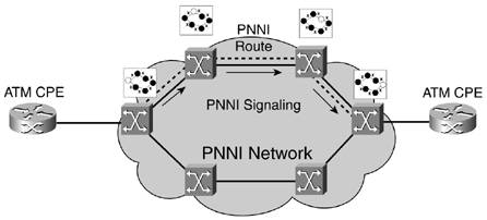
| PNNI has two major components: signaling and routing. Figure 8-12 shows an overview of how signaling and routing combine to facilitate SVC or SPVC calls. Figure 8-12. PNNI: Combining Signaling and Routing
The major goals of PNNI are as follows:
The goal is never to calculate an optimal route. Doing so would slow connection establishment as multiple iterations of the source routing algorithm were invoked. Instead, the source node (typically, the one that directly connects to the ATM CPE) uses its routing algorithm to identify the first route available that satisfies all the requested connection parameters. Also, in hierarchical PNNI scenarios, the network topology is summarized using node and link aggregation, so it might be impossible to find the best route. Instead, the trade-off is great scalability achieved by hierarchy. PNNI's routing component describes the ATM switch as a routing peer. It groups common peers into peer groups based on ID and ties common peers together using logical links. We will discuss these peers, groups, and links in detail shortly. PNNI details a routing hierarchy of nodes. This hierarchy can have a single level or, at most, 104 levels. A simple single-level hierarchy or flat network requires all ATM switches to maintain complete routing information regarding the states of all the nodes and links in the network. All the ATM switches in the network are in a single peer group when the PNNI network comprises a single level. As you probably suspect, the requisite amount of computational power and database memory per ATM switch grows as the number of nodes in the single-level hierarchy expands. Increasing the number of levels in the PNNI routing hierarchy helps stem this growth. A PNNI routing hierarchy allows an ATM peer to know the availability, reachability, and topology of its own PNNI peer group in detail and know that same information about other PNNI peer groups in general. Dispersing routing information throughout a PNNI network would never occur without PNNI's signaling component. In addition, the signaling component initiates and builds ATM virtual circuits through the PNNI network. Making use of existing standards, PNNI's signaling component is derived from the ATM UNI 4.0 specification previously developed by members of the ATM Forum. Taking its cue from a call setup request sent by a directly attached ATM UNI device, the signaling component within the ingress PNNI-controlled ATM switch builds a Designated Transit List (DTL). This DTL is a stack of instructions that tell all the downstream ATM switches how to route the virtual circuit through the PNNI network to the egress ATM switch. Because the DTL is implemented as a stack or "last in, first out" data structure, the top entry in the stack contains the route through the lowest-level peer group. Each subsequent stack entry contains the route through the next-level peer group. The bottom entry in the DTL stack contains the routing information needed to traverse the top level of the PNNI routing hierarchy. Note that in a multilevel DTL, only the lowest level or top stack entry contains detailed routing information such as node and link identifiers. The reason for this is that the ATM switch building the multilevel DTL has detailed topology information on only the node and link states in its peer group. If ATM virtual circuit establishment fails at some node or link listed in the DTL, the node that constructed the DTL must modify it and replace the existing route with a new one that skirts the failure point. The process of returning the failed virtual circuit call attempt upstream to the originating ATM switch is called crankback. Regardless of whether the call attempt fails because of switch hardware problems, transmission link outage, or switch resource overloads, the call attempt is cranked back to the source of the DTL. ATM virtual circuit connections are source-routed because the source switch that initiates the call establishment chooses the path through the network. The other ATM switches along the route just act on information listed in the received DTL. |
EAN: 2147483647
Pages: 149