ATM Call Signaling
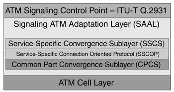
| PNNI was devised to distribute, organize, and store routing information to all destinations within a given ATM network. PNNI-controlled ATM switches build SVCs and Soft Permanent Virtual Circuits (SPVCs) using this routing information. To initiate, destroy, and restore these virtual circuits (VCs), a set of signaling protocol messages was invented to control the state of a given circuit. State diagrams dictate the actions performed on a given connection based on the received inputs. Well-defined and standardized state diagrams allow signaling to occur between equipment built by different manufacturers. SVC Signaling SpecificationsATM signaling occurs when one device wants to communicate its request or observation to another. Signaling occurs between switches and endpoints across a UNI interface or among switches inside a PNNI network. For signaling to be effective and efficient, the messages used in the signaling exchange must have an agreed-upon format, and they must be exchanged in a predefined order or protocol based on received inputs. The standards that define the message formats and protocol exchanges are shown in Figure 8-4. Figure 8-4. Parts of the ATM Signaling Stack
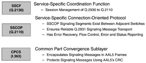
The standards are stacked on top of one another to emphasize that signaling messages are built from the top down. Figure 8-4 shows the Signaling ATM Adaptation Layer (SAAL) enveloping the Service-Specific Convergence Sublayer (SSCS), Service-Specific Connection-Oriented Protocol (SSCOP), and Common Part Convergence Sublayer (CPCS) because these comprise the sublayers of the SAAL. Figure 8-5 describes the function of each SAAL sublayer. Figure 8-5. Functions of the SAAL Sublayers
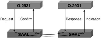
Layer-to-Layer CommunicationThe Q.2931 signaling layer is the source (origination point) and sink (termination point) of all signaling messages. This layer must exchange signaling messages or datagrams with peer layers in other PNNI nodes as well as with ATM end systems connected via UNI links. Messages originated in the Q.2931 layer flow downward through the SAAL sublayers to the ATM cell layer, where the formatted and packaged signaling message is segmented into cells and is transmitted over the physical layer. During this downward flow, the higher layer of the signaling stack communicates with the next lower layer using primitives. The four communication primitives are as follows:
Figure 8-6 shows the primitive exchange between the Q.2931 and SAAL layers in two ATM switches. Figure 8-6. Sample Primitive Exchange Between the Layers
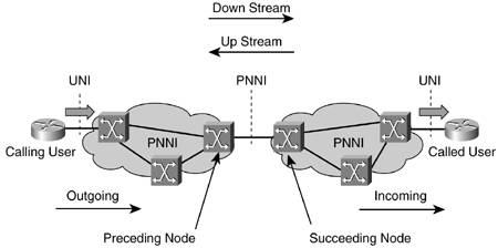
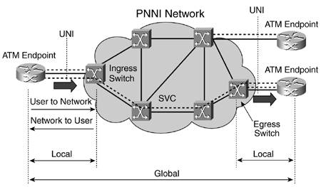
Reference PointsA few terms need defining before we can discuss end-to-end ATM virtual circuit creation and destruction. These terms clearly distinguish one end of the virtual circuit from the other. The calling party is the circuit endpoint that initiates the call; the called party is the endpoint that receives the call. Because circuits often route through multiple nodes on the way to the called party, the preceding node is any node that receives the virtual circuit setup/connect request and forwards it to another node. A succeeding node receives a setup/connect request from the preceding node. Finally, messages from the calling party to the called party flow in the "downstream" direction. Conversely, messages going the opposite way flow in the "upstream" direction. All these reference points are shown in Figure 8-7. Figure 8-7. Reference Points
We also need to define direction (user to network or network to user) and significance (local or global), as shown in Figure 8-8. Figure 8-8. Definition of Direction and Significance
Common Signaling MessagesVirtual circuits connected using the PNNI signaling procedures outlined in Section 6 of the PNNI 1.0 specification use the same procedures as those outlined in the ITU-T's Q.2931 signaling specification for B-ISDN DSS2 networks. The ATM UNI interface specification references this same document for virtual circuit creation and deletion. The Q.2931 document outlines a set of signaling messages used to set up and tear down connection as well as to verify the status of those connections. The following list categorizes these messages:
Now that the signaling message types are defined, it is important to know whether the calling or called party can initiate the message. In addition, if the calling and called party are separated by multiple ATM switches, it is important to know if a message has end-to-end/global significance or if it is only locally significant between two directly connected switches. Table 8-2 lists the message types, the initiators, and the significance of each message.
The additional message types for point-to-multipoint connections are shown in Table 8-3.
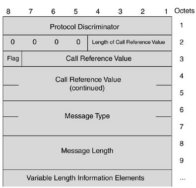
Signaling ChannelsBefore SVC signaling between two nodes commences, a dedicated AAL5 channel must be built between them. Signaling information regarding all dynamic ATM virtual circuit connections that traverse these two nodes passes over this channel. Every node in a PNNI network has a dedicated AAL5 signaling channel with each of its directly attached neighbor nodes with which it intends to construct dynamic ATM virtual circuits. Typically, VPI 0 and VCI 5 pass SVC signaling information if the entire VPI range is available. Optionally, if two nodes are linked via a VPC, associated signaling is employed, and the signaling VPI is the same as the VPC VPI value. The signaling VCI value remains 5 on the link unless the network administrator reconfigures it on the two nodes connected by the VPC. As soon as the signaling channels are established between neighbor nodes, dynamic VC setup can occur. Point-to-point call initiation begins when the preceding switch (in the case of an SPVC) or an originating end system (in the case of an SVC call) sends a setup message. The setup message and other Q.2931 messages contain information elements (IEs), which are formatted blocks within the message that enclose the parameters necessary to process the call. The setup message sent from a PNNI-controlled switch must contain at least the called party address, ATM traffic descriptor, Designated Transit List (DTL) (described in the section "PNNI Overview"), and broadband bearer capability information elements. The general signaling message format is shown in Figure 8-9. Figure 8-9. General Signaling Message Format
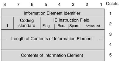
Each IE has the format shown in Figure 8-10. Figure 8-10. General IE Format
Section 6 of the PNNI 1.0 specification, "PNNI Signaling Specification," contains detailed information on the mandatory IEs contained in and the optional IEs allowed in each PNNI signaling message. Section 6 also defines the purpose and coding of every field in each IE used in PNNI signaling. Call Control TimersTimers start based on the sending or receiving of specific signaling messages. These timers ensure that the PNNI node's finite state machines for initiating and receiving dynamic virtual circuits are actively processing a call or are ready to. Table 8-4 lists the pertinent timers.
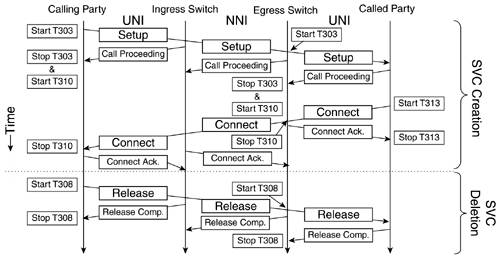
SVC Call CreationCall or virtual circuit creation begins when the preceding side sends a setup message to the succeeding side. When the preceding side sends a setup message, it simultaneously starts timer T303. A call proceeding, connect, or release complete message must be received from the adjacent downstream node before this timer expires. Otherwise, this timer is reset and the setup message is retransmitted for a second time. A second T303 expiration forces the initiating ATM switch to send a release complete message to the succeeding node. Typically, timer T303 is stopped by the receipt of a call proceeding message, and another timer, T310, starts at the preceding node. The receipt of a connect message stops T310 and moves the virtual circuit to the active state, but the receipt of an alerting message instead stops T310, commences timer T301, and transitions the virtual circuit state to alerting. Finally, the receipt of a connect message moves the call state from alerting to active and stops T301 if it was activated. SVC Call DeletionThe preceding or succeeding side of an active SVC begins the deletion procedure by sending a release message toward the opposite side of the connection. Each transit or tandem PNNI-controlled switch receiving the release message forwards it to the subsequent downstream node and transmits a release complete message upstream to the immediately preceding node. Whenever a node transmits a release message, it starts timer T308 and waits to receive either a release complete or release message. Unless both sides of a virtual circuit initiate a release at the same time, the node transmitting the release message receives a release complete message from the succeeding node. Please note that release messages have end-to-end significance, whereas release complete messages are significant only across the local link between two adjacent nodes. If T308 expires without the receipt of either message, the timer is reset, and the release message is retransmitted. As soon as the timer expires for a second time, the PNNI-controlled node releases the circuit without regard for the virtual circuit's state at downstream nodes. Figure 8-11 shows complete Q.2931 message flows for both SVC creation and deletion. Figure 8-11. SVC Creation and Deletion
|
EAN: 2147483647
Pages: 149