Interconnecting the Two PoPs
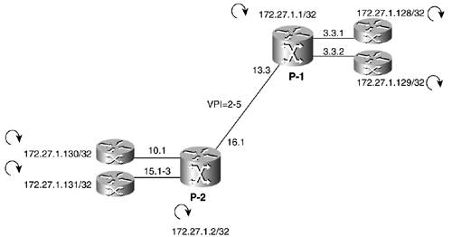
| This section shows how to configure the P-to-P link to interconnect the two PoPs, using the interfaces and VPI ranges shown in Figure 6-9. Figure 6-9. Connecting Two PoPs
Figure 6-9 also shows the MPLS view of the network. The LSC-switch connection (the control interface) is invisible (as if it were an internal bus). In general, all the ATM VC and VP switching functions are invisible to the MPLS control plane. The task is straightforward, and it is the same in both ends, so we will show only the IGX end. In a nutshell, we need to up a trunk, configure resources, and assign those resources to the LSC. All these tasks take place in the controlled switch. In the LSC, the configuration is the same as when configuring the LC-ATM interface toward an eLSR: create an XTagATM interface, link it to the port in the switch, and enable MPLS on it with an unnumbered IP. The resource partition in the IGX is as shown in Example 6-50. Example 6-50. Creating a VSI Resource PartitionP2-i8420 TN Cisco IGX 8420 9.3.30 Nov. 23 2001 20:44 GMT Trunk : 16.1 Maximum PVC LCNS: 256 Maximum PVC Bandwidth: 41000 (Statistical Reserve: 5000) State MinLCN MaxLCN StartVPI EndVPI MinBW MaxBW Partition 1: E 512 1000 2 5 50000 50000 Partition 2: D Partition 3: D Last Command: cnfrsrc 16.1 256 y 1 e 512 1000 2 5 50000 50000 Cnfrsrc successful. Next Command: Example 6-51 shows the LSC configuration in the URM LSC. Example 6-51. Label Switch Controller ConfigurationP2_LSC_URM_9#conf t Enter configuration commands, one per line. End with CNTL/Z. P2_LSC_URM_9(config)#interface xTagATM 161 P2_LSC_URM_9(config-if)#ip unnumbered loopback 0 P2_LSC_URM_9(config-if)#mpls ip P2_LSC_URM_9(config-if)#extended-port ATM 0/0 igx 16.1 P2_LSC_URM_9(config-if)#^Z P2_LSC_URM_9# Before we move on, I want to make an important point. The categorization of links in trunks and lines/ports belongs to the AutoRoute (AR) world. For a VSI master, an interface is a set of resources under its control. The VSI master, LSC in this case, does not know if the resource partition belongs to a trunk or a line/port in a BPX- or IGX-controlled switch. For the MPLS control plane, it makes no difference. So the configuration rule of thumb is to configure the link as a trunk only if AR will be enabled on it. Otherwise, configure it as a line. The special case is VP-Tunnel interfaces. They need to be configured as virtual trunks in the controlled switch. Example 6-52 introduces an extremely helpful show command to see that everything is working: show mpls atm-ldp summary. Example 6-52. Showing the ATM MPLS LSR SummaryP1_LSC_c7204#show mpls atm-ldp summary Total number of destinations: 6 ATM label bindings summary interface total active local remote Bwait Rwait IFwait XTagATM331 10 10 5 5 0 0 0 XTagATM332 10 10 5 5 0 0 0 XTagATM133 18 18 9 9 0 0 0 P1_LSC_c7204# P2_LSC_URM_9#show mpls atm-ldp summary Total number of destinations: 6 ATM label bindings summary interface total active local remote Bwait Rwait IFwait XTagATM101 10 10 5 5 0 0 0 XTagATM151 10 10 5 5 0 0 0 XTagATM161 18 18 9 9 0 0 0 P2_LSC_URM_9# We want the total number of bindings to be the same as the active number of bindings. In other words, no label bindings should be in a wait state (Bind Wait, Resource Wait, or Interface Wait). Table 6-2 describes these states.
If there's any destination with binding in bindwait, it can be pinpointed with the command show mpls atm-ldp bindwait. We can calculate the number of LVCs in the interfaces shown in the show mpls atm-ldp summary command output. Consider the interface XTagATM 133 in the P1 LSR. That interface divides the network into two sections, each with one LSR and two eLSRs. Those LSRs have eLSR functionality (they originate headend and terminate tailend LVCs), so they can be considered eLSRs for this calculation. Each eLSR on each side of the network sets up headend LVCs to all destinations on the other side. So the number of LVCs through a link that divides the network can be calculated like this:
where: ni equals the number of eLSRs on side i di equals the number of destinations on side i c equals the number of Classes of Service In our MPLS network at this time, each eLSR is advertising only one destination (its loopback IP address). So from the headend functionality, the number of LVCs equals the number of eLSRs on one side times the number of eLSRs on the other side. But each eLSR also terminates tailend LVCs from each eLSR on the other side, duplicating the number of LVCs. In summary, making the replacements n1 = d1, n2 = d2, and c = 1 (because there is only one Class of Service), the number of LVCs traversing the link is
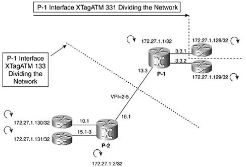
where: n1 equals the number of eLSRs on one side n2 equals the number of eLSRs on the other side Figure 6-10 shows how interfaces XTagATM133 and XTagATM331 divide the network. Figure 6-10. LC-ATM Dividing the Network
XTagATM133 has three eLSRs on each side, so the number of LVCs is 2 \dn4 * 3 \dn4 * 3 = 18. XTagATM331 has one eLSR on one side and five eLSRs on the other side, so the number of LVCs is 2 \dn4 * 1 \dn4 * 5 = 10. This line of reasoning can be generalized to quantifying and dimensioning the maximum number of LVCs in arbitrary networks, given that the worst case for a link with regards to the number of LVCs occurs when the network is divided in two. |
EAN: 2147483647
Pages: 149