IGX-8400-Based PoP
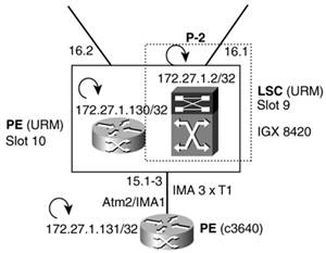
| The second PoP in our MPLS network is also made of an ATM LSR and two ATM eLSRs, as shown in Figure 6-8. Figure 6-8. IGX-8400-Based PoP
The LSR (P-2) is composed of an IGX-8420-controlled switch (16 slots) and a URM card acting as LSC. The URM-LSC is in slot 9. One of the eLSRs is another URM card in slot 10 in the IGX-8420, and the other eLSR is a Cisco c3640 router connected via a 3xT1 IMA link. The IGX-8400-based POP configuration is explored more fully in the following sections. The organization is the same as with the BPX-8600-based POP. The upcoming sections highlight the LSR and eLSR bringup, as well as an IMA-connected eLSR configuration. ATM LSR Bringup: IGX + LSCThe first step is to put together our LSR (P-2). As I mentioned, we will be using a URM card as a cocontroller card LSC. If we were to use an external router acting as LSC, only one preliminary step would be performed, and the rest would be exactly the same as with the URM: We would need to up the physical line to the external router using upln from the IGX and no shutdown from the router. The URM internal ATM interface cannot be shut down. We will start by adding (addport) and upping (upport) the URM port. See Example 6-37. Example 6-37. Adding and Upping a Port P2-i8420 TN Cisco IGX 8420 9.3.30 Nov. 23 2001 17:49 GMT Port: 9.1 [ACTIVE ] Interface: INTERNAL CAC Override: Enabled Type: UNI %Util Use: Disabled Speed: 353208 (cps) GW LCNs: 200 SIG Queue Depth: 640 Reserved BW: 0 (cps) Alloc Bandwidth: 353208 (cps) VC Shaping: Disabled Protocol: NONE Last Command: upport 9.1 14 UBUs allocated to slot 9. Allocation can be modified using cnfbusbw Next Command: We will also create a resource partition in the URM port (for VSI to control) using partition ID = 1. Refer to Example 6-38. Example 6-38. Creating a VSI Resource PartitionP2-i8420 TN Cisco IGX 8420 9.3.30 Nov. 23 2001 17:50 GMT Line : 9.1 Maximum PVC LCNS: 0 Maximum PVC Bandwidth: 0 State MinLCN MaxLCN StartVPI EndVPI MinBW MaxBW Partition 1: E 256 512 100 110 352898 352898 Partition 2: D Partition 3: D Last Command: cnfrsrc 9.1 0 0 y 1 e 256 512 100 110 352898 352898 Cnfrsrc successful. Next Command: Note that we did not use all the bandwidth for the VSI resource partition. We set aside 310 cells per second (CPS). This was done on purpose to reserve some bandwidth for the VSI protocol in the control interface (VSI master-slave VCs). We set aside those 310 CPS using the command cnfport, as shown in Example 6-39. The parameter Reserved BW supports a range of 0 CPS to 310 CPS. Example 6-39. Configuring the Port Reserved BandwidthP2-i8420 TN Cisco IGX 8420 9.3.30 Nov. 23 2001 17:51 GMT Port: 9.1 [ACTIVE ] Interface: INTERNAL CAC Override: Enabled Type: UNI %Util Use: Disabled Speed: 353208 (cps) GW LCNs: 0 SIG Queue Depth: 640 Reserved BW: 310 (cps) Alloc Bandwidth: 0 (cps) VC Shaping: Disabled Protocol: NONE Last Command: cnfport 9.1 N N N N 0 310 N Next Command: Finally, we add the controller using the command addctrlr. See Example 6-40. Example 6-40. Adding a VSI ControllerP2-i8420 TN Cisco IGX 8420 9.3.30 Nov. 23 2001 17:59 GMT VSI Controller Information CtrlrId PartId ControlVC Intfc Type CtrlrIP VPI VCIRange 1 1 0 40-54 9.1 MPLS 0.0.0.0 Last Command: addctrlr 9.1 1 1 0 40 Controller added successfully! Next Command: Now we can go to the LSC and finish the configuration. See Example 6-41. Example 6-41. Enabling VSI in the Label Switch ControllerP2_LSC_URM_9#conf t Enter configuration commands, one per line. End with CNTL/Z. P2_LSC_URM_9(config)#interface ATM 0/0 P2_LSC_URM_9(config-if)#label-control-protocol vsi id 1 base-vc 0 40 slaves 15 P2_LSC_URM_9(config-if)#^Z P2_LSC_URM_9# As before, we do not have to specify id and base-vc because we are using defaults. We also specify the slaves parameter. The slaves parameter indicates the number of VSI sessions that the LSC will use. In the case of an IGX-8430 with 32 slots, we need to specify slaves 31, or there will not be a VSI session and VSI master-slave VC for the higher-number slots (in the lower shelf). NOTE The number of slaves defaults to 14, so we do not need to change it for a BPX switch. For IGX switches, we specify a number of slaves equal to the number of slots in the IGX minus 1. Slots 1 and 2 (reserved for NPM controller cards) share one VSI VC because they are a redundant pair and only one is active at a time. On an IGX-8420, we configure 15 slavessession 0 for redundant slots 1 and 2 and sessions 1 to 14 for slots 3 to 16. Currently, NPM cards do not house a VSI slave. VSI communication is established, as shown in Example 6-42. Example 6-42. Showing the VSI SessionsP2_LSC_URM_9#show controllers vsi session Interface Session VCD VPI/VCI Switch/Slave Ids Session State ATM0/0 0 2 0/40 0/0 UNKNOWN ATM0/0 1 3 0/41 0/0 UNKNOWN ATM0/0 2 4 0/42 0/0 UNKNOWN ATM0/0 3 5 0/43 0/0 UNKNOWN ATM0/0 4 6 0/44 0/0 UNKNOWN ATM0/0 5 7 0/45 0/0 UNKNOWN ATM0/0 6 8 0/46 0/0 UNKNOWN ATM0/0 7 9 0/47 0/9 ESTABLISHED ATM0/0 8 10 0/48 0/0 UNKNOWN ATM0/0 9 11 0/49 0/0 UNKNOWN ATM0/0 10 12 0/50 0/0 UNKNOWN ATM0/0 11 13 0/51 0/0 UNKNOWN ATM0/0 12 14 0/52 0/0 UNKNOWN ATM0/0 13 15 0/53 0/0 UNKNOWN ATM0/0 14 16 0/54 0/0 UNKNOWN P2_LSC_URM_9#show controllers vsi session 7 Interface: ATM0/0 Session number: 7 VCD: 9 VPI/VCI: 0/47 Switch type: IGX Switch id: 0 Controller id: 1 Slave id: 9 Keepalive timer: 15 Powerup session id: 0x00000002 Cfg/act retry timer: 8/8 Active session id: 0x00000002 Max retries: 10 Ctrl port log intf: 0x00090100 ! LIN for 9.1 Trap window: 50 Max/actual cmd wndw: 10/10 Trap filter: all Max checksums: 19 Current VSI version: 2 Min/max VSI version: 2/2 Messages sent: 16 Inter-slave timer: 4.000 Messages received: 9 Messages outstanding: 0 P2_LSC_URM_9# Finally, we will create a loopback interface and assign the IP address 172.27.1.2/32 to it. We will also put together the initial MPLS configuration (enable CEF, enable LDP using the loopback IP as the router-id, and advertise the loopback under OSPF area 0) as shown in Example 6-43. Example 6-43. Initial MPLS ConfigurationP2_LSC_URM_9#conf t Enter configuration commands, one per line. End with CNTL/Z. P2_LSC_URM_9(config)#interface loopback 0 P2_LSC_URM_9(config-if)#ip address 172.27.1.2 255.255.255.255 P2_LSC_URM_9(config-if)#exit P2_LSC_URM_9(config)#ip cef P2_LSC_URM_9(config)#mpls ip P2_LSC_URM_9(config)#mpls label protocol ldp P2_LSC_URM_9(config)#mpls ldp router-id loopback 0 P2_LSC_URM_9(config)#router ospf 100 P2_LSC_URM_9(config-router)#network 172.27.1.2 0.0.0.0 area 0 To summarize, the BPX-8600 and the IGX-8400 configurations have some subtle differences between them. These differences are outlined in Table 6-1.
URM as eLSR ConfigurationThe eLSR configuration does not differ from the previous eLSR configuration in general terms. For the URM acting as eLSR, we have an internal port that we need to add (addport) and then up (upport). We configure a resource partition in URM port 10.1 using the same partition ID as the LSC. At this point (see Example 6-44), the LSC discovers this interface it has to control and all its resources. Example 6-44. Showing a VSI Resource Partition from the LSCP2_LSC_URM_9#show controllers vsi descriptor | begin 10.1 Phys desc: 0.10.1.0 Log intf: 0x000A0100 ! The slave resides in the URM card in slot 10. Interface: XTagATM101 IF status: n/a IFC state: ACTIVE Min VPI: 50 Maximum cell rate: 253208 Max VPI: 52 Available channels: 512 Min VCI: 32 Available cell rate (forward): 253208 Max VCI: 65535 Available cell rate (backward): 253208 P2_LSC_URM_9# From the LSC, we create an extended MPLS ATM interface, enable MPLS on it, configure the IGX port mapping, and unnumber its IP address to the loopback. Refer to Example 6-45. Example 6-45. Creating an Extended MPLS ATM InterfaceP2_LSC_URM_9#conf t Enter configuration commands, one per line. End with CNTL/Z. P2_LSC_URM_9(config)#interface xTagATM 101 P2_LSC_URM_9(config-if)#ip unnumbered loopback 0 P2_LSC_URM_9(config-if)#mpls ip P2_LSC_URM_9(config-if)#extended-port ATM 0/0 igx 10.1 P2_LSC_URM_9(config-if)#end P2_LSC_URM_9# We finish with the eLSR URM configuration in an MPLS subinterface of the internal ATM port adapter (PA ATM0/0), as shown in Example 6-46. Example 6-46. Configuring the PE SubinterfacesPE_URM_10#conf t Enter configuration commands, one per line. End with CNTL/Z. PE_URM_10(config)#ip cef PE_URM_10(config)#mpls ip PE_URM_10(config)#mpls label protocol ldp PE_URM_10(config)#interface loopback 0 PE_URM_10(config-if)#ip address 172.27.1.130 255.255.255.255 PE_URM_10(config-if)#exit PE_URM_10(config)#mpls ldp router-id loopback 0 PE_URM_10(config)#interface atM 0/0.1 mpls PE_URM_10(config-subif)#ip unnumbered loopback 0 PE_URM_10(config-subif)#mpls ip PE_URM_10(config-subif)#mpls atm vpi 50-52 PE_URM_10(config-subif)#exit PE_URM_10(config)#router ospf 1 PE_URM_10(config-router)#network 172.27.1.130 0.0.0.0 area 0 PE_URM_10(config-router)#^Z PE_URM_10# It is important to note that we use the subinterface-level command mpls atm vpi to instruct the eLSR to use the VPI range configured in the resource partition, 50 to 52. As you know, the LSC learns those values from the VSI slave. IMA-Connected eLSR ConfigurationThe configuration of the external eLSR that is connected via a 3xT1 IMA link is in essence the same as with the URM. The first difference, as shown in Example 6-47, is that we need to up the IMA lines from the IGX first. Example 6-47. Upping IMA LinesP2-i8420 TN Cisco IGX 8420 9.3.30 Nov. 23 2001 18:39 GMT Line Type Current Line Alarm Status 15.1(3) T1/71 Clear - OK Last Command: upln 15.1-3 256 LCNs allocated. Use 'cnfrsrc' to configure LCNs Next Command: NOTE The 3 x T1 line has a usable bandwidth of 71 DS0s. This is because 1 DS0 is being used by the IMA protocol. In other words, 3 times 24 DS0s minus 1 DS0 equals 71 DS0s. The LSR configuration after this is the same. We upport 15.1, we configure resources for the use of VSI (using VPI range 5 to 10), and we create the Extended MPLS ATM interface in the URM LSC. Likewise, from the c3640 configuration, the only difference is that we need to create the IMA group first. See Example 6-48. Example 6-48. Configuring an IMA InterfacePE_3640#conf t Enter configuration commands, one per line. End with CNTL/Z. PE_3640(config)#interface ATM 2/0 PE_3640(config-if)#ima-group 1 PE_3640(config-if)#no shut PE_3640(config-if)#interface ATM 2/1 PE_3640(config-if)#ima-group 1 PE_3640(config-if)#no shut PE_3640(config-if)#interface ATM 2/2 PE_3640(config-if)#ima-group 1 PE_3640(config-if)#no shut PE_3640(config-if)#exit PE_3640(config)#interface ATM 2/IMA1 PE_3640(config-if)#^Z PE_3640# The rest of the configuration is the same as creating a subinterface of ATM2/IMA1, except that we need to specify the VPI range in the eLSR with the interface-level command mpls atm vpi. Refer to Example 6-49. Example 6-49. Specifying the LC-ATM VPI RangePE_3640(config)#interface ATM 2/IMA1.1 PE_3640(config-subif)#mpls atm vpi 5-10 |
EAN: 2147483647
Pages: 149