ATM MPLS Network Components
| The following components are involved in an ATM MPLS network:
Conceptually, MPLS is based on separate routing and forwarding paradigms. Naturally, a one-to-one relationship or mapping with the multiservice switching architecture separates the controller and the controlled switch (as discussed in Chapter 1, "What Are Multiservice Switching Networks?"). Therefore, it is like a complete match, and it makes perfect sense to directly relate the two. That is why a multiservice switching ATM-LSR is made up of an LSC that takes care of the routing portion and a controlled virtual switch with a subswitching fabric that is responsible for the forwarding. Label Switch ControllerThe LSC is in essence a router that has two types of interfaces associated with MPLS:
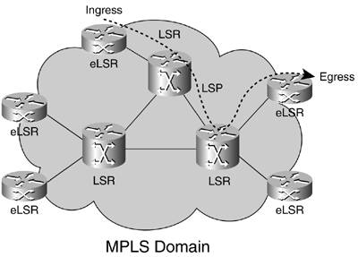
VSIUsing VSI, an ATM switch can be controlled independently by multiple controllers, such as PNNI and MPLS, each having a different and independent control plane. This is possible because different control planes use different partitions of the switch resources. When a virtual interface is activated on an entity such as a port, trunk, or virtual trunk for use by the LSC, the resources of the virtual interface associated with that entity are made available to the controller. VSI requires a dedicated interface on the LSC and ATM switch for its exclusive use. Hence, it cannot be shared with ATM Forum connections. All related VSI information was covered in Chapter 2, "SCI: Virtual Switch Interface," and Chapter 3, "Implementations and Platforms." LC-ATMAn LC-ATM interface is an ATM interface controlled by the LSC. When a packet traversing such an interface is received, it is treated as a labeled packet. The packet's top label is inferred from either the contents of the VCI field or the combined contents of the VPI and VCI fields. Any two LDP peers that are connected via an LC-ATM interface use LDP capability negotiations to determine which of these fields is applicable to that interface. XTagATMFrom the LSC's point of view, associated label-switched ports (LC-ATMs) on the ATM switch are represented as a Cisco IOS interface type called extended label ATM (XTagATM). LC-ATM ports on the ATM switch are essentially any interfaces that carry packets as ATM cells on LVCs controlled by MPLS. This would include a virtual path connection (VPC) whose opposite endpoint is an edge LSR or another ATM switch (which in turn has eLSR connections). The XTagATM interfaces could be viewed as virtual ATM interfaces or ATM tunnels, but they can carry only MPLS-related traffic, and they represent interfaces external to the LSC. No ATM Forum connections can be defined on them. It is worth noting that the XTagATM interface on the LSC does not actually carry customer data cellsthe switch does. XTagATM interfaces are used to transport control information such as the LDP and the interior routing protocol between participating label switch routers (LSR or eLSR types). Each XTagATM interface maps to a physical interface or virtual trunk endpoint on the switch. The signaling VCs from that interface are cross-connected to the LSC control interface and terminate on the XTagATM logical interface. In this way, the LSC can participate in the MPLS signaling for each physical or virtual trunk interface. Data traffic from each physical interface is generally cross-connected through the switch without passing through the LSC. The exception to this general rule is traffic whose source or destination is the LSC itself, as well as routing updates or label distribution information. The adjacent node on an LSC XTagATM interface is any router or switch acting as an LSR or eLSR. On every XTagATM interface, VCI 32 within the defined tunnel is used by default for routing and signaling. This topic is covered extensively in Chapter 3. ATM-LSRATM-LSR is an LSR with a number of LC-ATM interfaces. It forwards cells between these interfaces using labels carried in the VCI or VPI/VCI field and without reassembling the cells into frames before forwarding. When two ATM-LSRs are connected via an LC-ATM interface, a non-MPLS connection, responsible for carrying unlabeled IP packets, must be available. This non-MPLS connection is used to carry LDP packets between the two peers and also is used for other unlabeled packets (such as interior routing packets). The non-MPLS connection uses the LLC/SNAP encapsulation, defined in RFC 1483 and RFC 2684. VCI values 0 through 32 are reserved for control traffic and should not be used by an LC-ATM interface as a label. These unlabeled packets use standard AAL5 encapsulation, as defined in RFC 1483. The default VPI/VCI value for an unlabeled packet is VPI 0 VCI 32. With the exception of these reserved values, the VPI/VCI values used can be treated as independent spaces. The allowable ranges of VPI and VCIs are communicated through LDP. You can also connect two LSRs via an ATM VP, as in the case where an ATM cloud connects the two LSRs via an ATM virtual path. In this case, the VPI field is unavailable to MPLS, and the label must be encoded entirely within the VCI field. Again, VCI ranges 0 to 32 cannot be used for LVCs. The VPI value must be configured for a predefined VPI set by a virtual path over ATM. In all cases, LVCs use ATM null encapsulation, as defined in RFC 1483 and RFC 2684. The control-vc, using VPI/VCI 0/32 by default, uses AAL5SNAP encapsulation. Frame-Based LSRFrame-based LSR is an LSR that forwards complete frames between its interfaces. Note that such an LSR can have zero, one, or more LC-ATM interfaces. Sometimes a single box might behave as an ATM-LSR with respect to certain pairs of interfaces but might behave as a frame-based LSR with respect to other pairs. For example, an ATM switch with an Ethernet interface might function as an ATM-LSR when forwarding cells between its LC-ATM interfaces but might function as a frame-based LSR when forwarding frames from its Ethernet to one of its LC-ATM interfaces. ATM-Edge LSRAn ATM-edge LSR is an LSR that is connected to an ATM-LSR by LC-ATM interfaces and that resides at the edge of the MPLS network. An eLSR does not switch labels; it switches IP packets to labels and labels to IP packets. A packet-based LSR is a device that manipulates whole packets rather than cells. A router running packet-based MPLS is a packet-based LSR. An ATM-edge LSR is also a type of packet-based LSR. A traditional ATM switch can support ATM MPLS within a permanent virtual circuit (PVC), which acts as a point-to-point interface. In this case, the traditional ATM switches do not actually perform multiprotocol label switching. They merely support "tunnels" through which MPLS packets are carried. All the MPLS network components are shown in Figure 4-6. Figure 4-6. MPLS Network Components
|
EAN: 2147483647
Pages: 149