How Label Switching Works
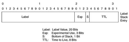
| The multiprotocol label-switching architecture is defined in RFC 3031. In general terms, label switching in the data path is similar in concept to VC switching in traditional ATM switches. At each switching juncture, the label value is rewritten with an outgoing label, similar to ATM cell switching. The main difference is in the control plane, because LDP is used for label setup as opposed to ATM forum signaling. The general label that is used for label swapping, also called a shim header, resides in the label stack, as defined in RFC 3032, "MPLS Label Stack Encoding." The shim header is a 32-bit header added in front of the IP header, as shown in Figure 4-2. All link types, including ATM and Frame Relay, insert this special shim header. Figure 4-2. Label Stack Entry
The fields in the shim header shown in Figure 4-2 are as follows:
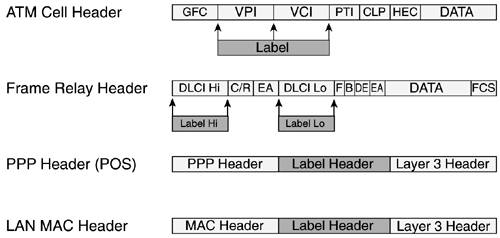
The 20-bit label is used for label swapping. This MPLS header or stack of entries appears after the data link layer headers and before the network layer headers. For this reason, the MPLS header is normally called Layer 2-and-a-half (Layer 2 1/2). It is used in frame-based data link layers such as PPP, Ethernet, and Fast Ethernet. However, ATM and Frame Relay already implement a label-switching forwarding mechanism, swapping identifiers (VPI/VCI and DLCI) on a link-by-link basis. Therefore, it makes sense to use these identifiers as the labels swapped in MPLS. On ATM MPLS, the VPI and VCI fields or the VCI field alone are used as the label. This is defined in RFC 3035, "MPLS Using LDP and ATM VC Switching." In Frame Relay-based MPLS, as defined in RFC 3034, "Use of Label Switching on Frame Relay Networks Specification," the DLCI is used as the label. Figure 4-3 shows the different label stack entries using different Layer 2 protocols. Figure 4-3. Encapsulation in Different Layer 2 Protocols
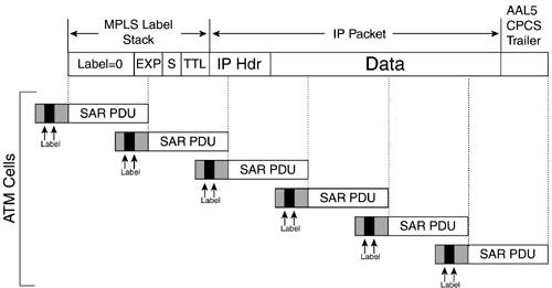
VPI/VCI fields or VCI fields alone are used as the label. Labels are applied to each cell, which makes label swapping look like ATM switching from a forwarding perspective. Both Label Distribution Protocol (LDP, as defined in RFC 3036) and Tag Distribution Protocol (TDP, the Cisco proprietary prestandard distribution protocol) are used for label distribution in ATM on the control plane. On label switching controlled ATM (LC-ATM) interfaces, label packets are sent using null encapsulation, as defined in Section 6.1 of RFC 2684, in which there is no need for protocol identification. The label stack header is always attached preceding the network layer header before segmenting the packet into cells. In this case, the label stack header carries a null label because, as you know, the top label is carried encoded in the VPI/VCI or VCI only fields. Why carry this shim header if the label is encoded in cell headers? The main reason is to allow a label stack of arbitrary depth, just as on non-ATM links. Another function of the label stack is to carry the TTL and Exp bits. You need both of these fields if a packet is to be label-switched further by a nonATM-LSR. This function also provides transparency for the Exp bits. In summary, labeled packets must always have a shim. The complete encapsulation of ATM MPLS labeled packets is shown in Figure 4-4. Figure 4-4. MPLS Encapsulation on LC-ATM
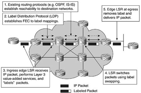
The ATM MPLS packet shown in Figure 4-4 contains a stack of one label entry, the MPLS label. This would be a packet terminating in an LSR or eLSR. In an MPLS VPN application, the MPLS packet inside the AAL5 PDU has at least two entries in the label stack even when it is carried on a label virtual circuit (LVC): an implicit-null label (since the MPLS label is carried in the VPI/VCI fields), and the BGP VPN label. This will be discussed in detail in the upcoming section "IP Virtual Private Network Services." MPLS Operation ExampleLet's look briefly at a very basic and general MPLS operation example, as shown in Figure 4-5. At this stage, this example applies to both frame-based and cell-based MPLS. Figure 4-5. How MPLS Works
We can divide the process in two planes well-separated by MPLS:
The things you need to notice here are that labels have only local significance, meaning that they are meaningful in the link only and not network-wide. That is normally the difference between an identifier, which is locally significant, and an address, which is globally significant. A key point to remember is that MPLS provides a clean separation between routing (in the control plane) and forwarding (in the data plane), as opposed to normal IP routing, in which both routing and forwarding are almost indivisible. A frame-based MPLS implementation and a cell-based MPLS implementation have some important differences:
|
EAN: 2147483647
Pages: 149