Protected Services Access
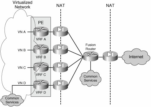
| To allow secured communication across VNs and between VNs and shared services, you must create unique points of ingress and egress to and from each VN. You can do so easily by configuring the routing inside each VN to forward traffic destined outside the VN to a specific gateway. After traffic reaches this gateway, it can be controlled by means of access control lists (ACLs), firewalls, intrusion detection systems (IDSs), or any other in-band security mechanism that is considered necessary. This is equivalent to treating each VN as if it where a physically separate network. When connecting separate networks to a common resource, each network must be headended by a security device to control access to the network. The device typically used is a firewall. When accessing the Internet, the place in the network where such a firewall is deployed is known as the Internet edge. When referring to other services beside the Internet, you will see this as the VN perimeter rather than the Internet edge. If you are thinking they are similar and could be one and the same, you are on the right track. Figure 8-9 illustrates a typical perimeter deployment for multiple VNs accessing common services. Figure 8-9. Central Site Providing VPN Perimeter Security As shown in Figure 8-9, each VN is headended by a dedicated firewall. This allows the creation of security policies that are specific to each VN and independent from each other. To access the shared services, all firewalls are connected to a "fusion" router. The fusion router can provide the VNs with connectivity to the common services, the Internet, or even inter-VN connectivity. The presence of this fusion router should raise two main concerns:
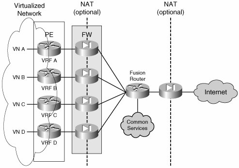
The presence of dedicated firewalls at the perimeter of each VN prevents the leaking of traffic between VNs through the fusion router by allowing only established connections to return through the VN perimeter. The key is to configure the routing on the fusion device so that routes from one VN are not advertised to another through the fusion router. The details of the routing configuration at the central site are discussed in the "Multiple Common Services/Internet Edge Sites" section. Figure 8-9 also shows an additional firewall separating the fusion area from the Internet. This firewall is optional. Whether to use it depends on the need to keep the common services or transit traffic in the fusion area protected from the Internet. Although the following discussion focuses mostly on providing Internet access, it can be generalized to provide access to any external resource for a VN. An external resource can also include resources in other VNs; thus, a resource in VN D is considered an external resource for VN A, and therefore that resource can be accessed through the secure VN perimeter. Firewalling for Common ServicesAs VNs proliferate, headending each VN onto its own firewall can become both expensive and hard to manage. Cisco Firewalls can be virtualized and thus offer a separate context for each VN on the same physical appliance. The resulting topology is depicted in Figure 8-10. The difference between this topology and those shown in previous figures is that a single physical firewall now provides a dedicated logical firewall to each VN. Figure 8-10. Virtual Firewall Contexts The concept of virtual firewalls or firewall contexts has been implemented on Cisco Firewall appliances and in the integrated Firewall Service Module (FWSM) for the Cisco Catalyst 6500. The integration of the firewall functionality onto the PE platform allows the topology depicted in Figure 8-9 to be consolidated onto a single physical device, as shown in Figure 8-11. The logical topology remains unchanged: The firewall functionality is carried out by a FWSM within the PE, and the fusion router is implemented by the creation of a VRF inside the same PE. Note that the "fusion" VRF does not connect to the VN as a separate router. Figure 8-11. Single-Box Implementation of the VPN Perimeter Gateway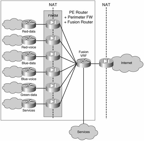 A single-box perimeter implementation is feasible when there is a single common services/Internet site. However, when there is more than one services site and both resiliency and load distribution are desired among those sites, it is necessary to move the fusion VRF outside the PE router and use a separate physical fusion router (mostly because of the need for separate router IDs and separate BGP processes to provide the desired resiliency through appropriate external BGP [eBGP] peering). An alternative to deploying separate routers is provided by the use of Cisco IOS features that can allow eBGP relationships within a single platform. The topologies and necessary routing configuration for single-and multiple-service site support are discussed in the section on "Routed Firewall Deployments." Routed Firewalls and Transparent FirewallsBoth firewalls and virtual firewall contexts can operate in one of two modes:
Each mode requires careful design and configuration of the routing between the VRFs and the fusion router. We explore these subtleties in the next few sections. Routed Firewall DeploymentsFirewalls can be used in routed mode, but their routing capabilities are limited when compared to those of a proper router. Therefore, special considerations must be made to integrate a routed firewall into any network. When firewalls are virtualized, their routing feature set is even more restrictive. Because of capacity limitations, most firewalls that can be virtualized do not support dynamic routing when virtualized. We will analyze the integration of virtual firewalls in a network with a single Internet edge and in a network with dual Internet connectivity. Note To illustrate the concepts in this section, a VN deployment based on MPLS VPNs has been chosen. The concepts apply to any VN type of deployment and are not limited to MPLS VPN based VNs. The few differences are in the redistribution of default routes into the VN space and the load balancing considerations inside the VN space. The terms VN and VPN may be used interchangeably throughout this section. Single Common Services/Internet Edge SiteThe routing between the fusion router, the different contexts, and the VNs must be configured with care. Because of its place in the topology, the fusion router has the potential to mix the routes from the different VNs when exchanging routes dynamically with the different VNs. However, because a firewall in routed mode supports only static routing when configured for multiple contexts, the mixing of VN routes is not a concern. Connectivity between VNs is achieved by the sole configuration of the fusion router; however, the firewalls are configured to allow established connections only; that is, to allow only connections initiated from the inside of the firewall. Therefore, all VNs can reach the fusion router, and the fusion router can return traffic to all the VNs, but the VNs cannot communicate with each other through the fusion router unless specific policies are set on the different firewall contexts to allow inter-VN communication through the VN perimeter gateway. The static routing configuration for the perimeter gateway is summarized in Figure 8-12 and described in the steps that follow. The detail is provided only for one VN (VN red-data); other VNs will require similar configuration. Figure 8-12. Routing Considerations at the VN Perimeter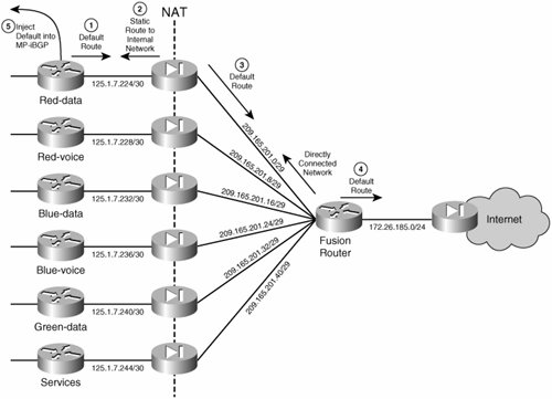
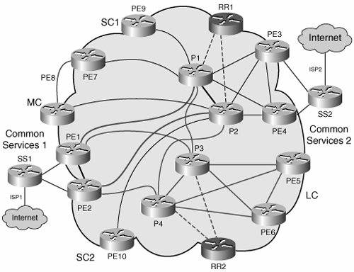
Note MPLS VPNs use MP-iBGP to carry the routing information in each VN. Step 5 shows how to redistribute the default route into MP-iBGP. Other VN techniques, different from MPLS VPNs, use IGPs such as EIGRP or OSPF to carry VN routing information. In these cases the redistribution of the default routes is done into the IGP instances corresponding to the different VNs. This procedure enables us to integrate the firewall with static routing and still have a default route dynamically injected into the VPNs. The next section discusses how to deploy multiple Internet access points and have them back up each other. Multiple Common Services/Internet Edge SitesMultiple sites are usually deployed for access to the Internet, and therefore we focus our discussion on Internet access. However, as mentioned previously, the same principles apply for other shared services that are accessible over a common network. When you are using multiple access points to the Internet (or the common services area), resiliency is one of the main goals, along with load balancing. The proposed solution uses two common services sites, each of which injects a default route into each virtual network (VN). As the default routes are received at the different PEs, the preferred route is chosen by the PE based on its proximity to the common services sites. This proximity is determined based on the metric of the interior gateway protocol (IGP) running in the core of the network (all other BGP attributes should be equal between the two advertised default routes). In the particular case of Internet access, some sites will use the first Internet edge site and others will use the second based on their proximity to one Internet edge site or another. This achieves site-based load balancing and minimizes the use of the internal enterprise links by choosing the closest Internet gateway to send traffic to the Internet in the most efficient manner. Figure 8-13 shows a sample topology. Figure 8-13. Internet Edge Sites and IGP Proximity In the case where one Internet edge site dies, all Internet traffic should be rerouted to the live Internet site. For failures that occur within the enterprise network, this failover is provided by the reconvergence of the core IGP and the overlaid MP-iBGP. However, because we are injecting static default routes into the VNs, if the failure is in the ISP, this failure will remain undetected and traffic will be blackholed unless there is a dynamic mechanism to report this failure and trigger a routing reconvergence to use the second Internet edge site. To do this, a dynamic routing protocol can be used to conditionally inject the default routes into the VNs. This means that a default route is originated and injected into a VN from the Internet edge router if, and only if, this route is validfor example, if the route exists in the edge router table (see Step 8 below). To achieve this dynamic notification over the perimeter firewalls, eBGP can be used to establish a connection across the firewall contexts (contexts do not support dynamic routing protocols). Figure 8-14 summarizes the routing relationships. Because eBGP peering is required, and this cannot be established between VRFs in a single box, a separate physical router is required for the fusion role. Figure 8-14. Internet Edge Sites and IGP Proximity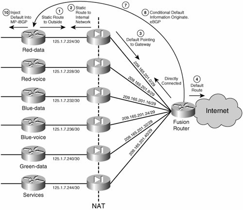 The following steps must be completed to achieve the necessary BGP peering and inject the default routes conditionally:
We have discussed how to integrate routed firewalls for the single edge and redundant Internet edge scenarios. The mechanisms and topology discussed were tested and documented using a separate physical router to act as the fusion router. In theory, you could use a VRF to play the role of fusion router, and thus it may be possible to collapse the entire topology into a single device. This, however, requires special functionality. A separate router might be required for two main reasons:
With upcoming Cisco IOS versions, these requirements will be addressed by features that allow the rewrite of router IDs per VRF and the creation of multiple BGP process IDs for each VRF. The changes will allow the deployment of the logical topology discussed within a single physical router. In any case, the routing principles to use are the same. Routing ConsiderationsThe following two sections discuss some routing details that you need to keep in mind when deploying the Internet edge as discussed. Advertising Multiple Routes into MP-iBGPAdvertising more than one default route or advertising multiple routes for the same prefix must be done with care. The default behavior of a route reflector (RR) is to make a decision based on metrics and attributes and reflect only the best one of the advertised routes. The result is that all PEs will always receive the route that is best for the RR, which is not necessarily the best route for the PE to reach the Internet. To achieve load balancing and redundancy from injecting multiple routes for a common destination in our topology, it is important that the RR actually reflects all the routes it receives, so that the route selection can actually be done at the ingress PEs. To achieve this, the routes must be advertised with different RDs. For example, in Figure 8-13, the default route advertised by Common Services Site 1 (SS1) is sent with an RD of 10:103; the default route sent by Common Services Site 2 (SS2) is sent with an RD of 101:103. In this manner, some sites will prefer SS2; others will prefer SS1, based on proximity. Load balancing across the enterprise core can be achieved by instructing BGP to install multiple paths in the routing table (ibgp multipath). It is tempting to use unequal-cost paths and load balance across all possible paths. However, doing so can affect the way traffic to the Internet is handled and can cause the use of suboptimal paths to access the Internet. Note The considerations here discussed for load balancing with iBGP do not apply when using Equal Cost Routing within IGPs in a non-MPLS VN deployment. In the proposed scenario, the requirement is for certain portions of the network to prefer one Common Services Site over another. Therefore, the load balancing is done per site, rather than per flow. For instance, site SC1 would always try to use SS1 first because it is the closest Internet access site. On the other hand, if unequal paths are allowed to be installed in the routing table, SC1 would send some flows over SS1 and others over SS2, potentially congesting low-speed links that would not be used if only one path had been installed on the routing table. However, the best solution is hardly to turn BGP multipath off, but to set the BGP multipath capability to install only multiple equal-cost paths. This is important because equal-cost load balancing is desirable between sites. Because only equal-cost paths can be installed in the table, the Internet will be accessed consistently via either SS1 or SS2 depending on the proximity of the site. If a failure is detected, the routing protocols must determine which sites are still available and recalculate the paths to the Common Services Sites to make a decision on where to exit to the Internet. Asymmetric Return PathsA classic problem faced when multihoming to the Internet is when traffic exits the enterprise out of one gateway and the return traffic is received over a different gateway. The implications are many, the main one being that the return traffic would normally not be able to get through the firewall because there would not be a session established at the return firewall because the traffic originally left the network through a different firewall. In the proposed scenario, the asymmetry of the return path is handled by using different global NAT address pools outside the different Internet gateways. Each Internet gateway advertises a unique address pool, thus eliminating ambiguity in the return path. For example, the source address of traffic leaving SS1 is rewritten to a prefix advertised only by SS1. Therefore, the return traffic for a stream that entered the Internet through SS1 would have to come through SS1 because the Internet has routes to the SS1 address pool only through SS1. Network Address Translation (NAT)When operating in routed mode, a firewall establishes a connection between the inside and the outside for each flow that is to traverse the firewall. These connections are in the form of NAT entries, regardless of address translation being or not being configured on the firewall. The default behavior of firewalls is to allow the establishment of flows that are initiated from the inside network. Provided that the ACLs allow it, upstream traffic should flow through the firewall without a problem. For the return path, however, a valid NAT entry in the connection table is required for the firewall to allow return traffic through. This NAT entry is dynamically created when the flow is initiated from the inside; connections initiated from the outside will not dynamically create an entry in the firewall. This unidirectional mechanism prevents connections from being initiated from the outside the network. For a connection to be successfully initiated from the outside of the network, a NAT entry for the internal destination address should exist in the firewall table before the connection can be established. Therefore, if connections initiated from the outside network are required, static NAT entries must be created to make the specific prefixes available to the outside of the firewall. To allow outside initiated connections, the creation of a static NAT entry is necessary, even if the firewall is configured to not translate addresses (nat 0). Benefits of NATBeing able to translate addresses confers many benefits. The main ones can be summarized as follows:
Dynamic NATAddress translation can be done dynamically. When an inside station attempts to connect to a site outside the firewall, a dynamic mapping of the source address of the inside station to a globally (outside) significant address is made. The globally significant address to be used is defined by a configured address pool. Therefore, each connection is identified by a unique NAT entry. However, there is the potential for the number of connections to exceed the number of addresses available in the translation pool, in which case any new connection would not be successful. An alternative to regular NAT is Port Address Translation (PAT). With PAT, you can use a single IP address for the global pool. Multiple connections can be associated to the same IP address and will be uniquely identified by a unique Layer 4 port number. Thus, a single global address can accommodate thousands of connections. Static NATWhen internal resources must be made available outside the firewall, you must provide a predictable presence for the internal resource on the outside of the firewall. By default, all addresses internal to the firewall are not visible to the outside. When addresses are not being translated, they might be visible to the outside, but they still would not be reachable, because reachability from the outside requires an entry in the firewall connection table to be present ahead of time. Static NAT assigns a globally significant address to the internal resource and adds an entry to the firewall connection table. This address is fixed so that it can be reached from the outside in a consistent manner. The entry in the connection table makes it possible for the outside to connect to the inside resource provided that the necessary policy is in place. NAT in the VN PerimeterA combination of dynamic and static NAT is required at the VN perimeter. Dynamic NAT is used to allow connectivity for sessions established from the inside of the network. Static NAT is required to allow BGP peer establishment and connectivity to resources shared from inside a service VN. Dynamic NAT can be established by using either NAT or PAT. When using NAT, you must provide the outside interface of the firewall with an IP prefix that can accommodate the entire global address pool to be used in the translation. Figure 8-15 shows the scenario for the red-data VN in our example. Figure 8-15. NAT for the Red VN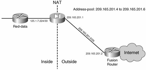 Each connection from the red-data VN to the Internet creates one NAT entry and therefore uses one of the addresses in the address pool. Thus, the number of possible concurrent connections is limited to three in this specific scenario. Notice that a 29-bit address mask (rather than 32 bits) has been used for the point-to-point connection to accommodate the NAT address pool. The commands in Example 8-9 configure the red-data firewall context to allow this kind of connectivity. Example 8-9. Dynamic NAT with a Finite Global Address Pool
Alternatively, PAT can provide dynamic translation without the limitation of the exhaustion of the global address pool. Configuring PAT is almost identical to configuring NAT; the difference is that instead of defining a global range, a single IP is configured, as demonstrated in Example 8-10. Example 8-10. Port Address Translation Allows Many-to-One Address Translations
A static NAT entry is required to allow BGP peering between the fusion router and the internal VRF. The necessary ACLs must be configured to allow this type of connectivity, too. Care must be taken to open the firewall exclusively to the relevant BGP traffic. The configuration shown in Example 8-11 takes care of this. Example 8-11. Static NAT Entries Allowing BGP Peering Through the Firewall
Other static NAT entries may be required if servers inside a VN will be made available outside the VN. As the number of servers to publish increases, the use of static PAT may come in handy. For detailed information on static PAT and more details on NAT in general, see the FWSM configuration guide at http://www.cisco.com/univercd/cc/td/doc/product/lan/cat6000/mod_icn/fwsm/fwsm_2_2/fwsm_cfg/index.htm. Transparent Firewall DeploymentsWhen NATing is not necessary, you can use the firewalls in transparent mode. This mode simplifies the routing significantly, allowing complete functionality to be achieved by means of dynamic IGPs. Figure 8-16 summarizes the routing relationships necessary at the VN perimeter. This setup is as simple as having all VRFs peer with the fusion router/VRF. The fusion router will inject a default route into the IGP, and this will be redistributed into MP-iBGP at the PE. Figure 8-16. Transparent Firewalling at the VPN Perimeter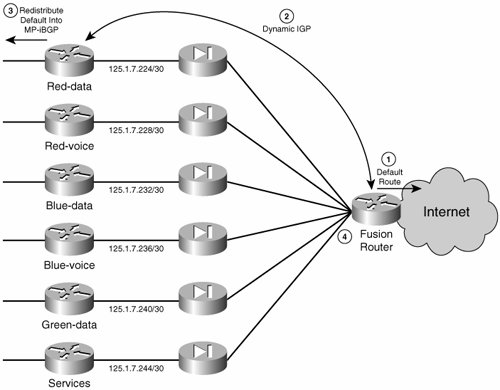 Because of the bridged nature of the firewalls, you can establish the peering between the VRFs and the fusion router directly with an IGP. On the other hand, you cannot use the firewalls for NAT, and therefore all VRFs must use valid and unique IP address spaces. The configuration is simple and consists of the following steps. This is standard Internet edge configuration and must be done for each VN.
The communication between VRFs is prevented by the default behavior of the firewall, which allows only internally initiated connections. Therefore, with the default firewall policies, a connection initiated from RED to BLUE will be allowed through the RED firewall context, but will be rejected by the BLUE context because it would be considered an externally initiated connection. Nevertheless it is recommended to keep the routes from being populated across VRFs and allow these updates through only when inter-VRF communication is desired. |
EAN: 2147483647
Pages: 128
- ERP Systems Impact on Organizations
- The Second Wave ERP Market: An Australian Viewpoint
- Enterprise Application Integration: New Solutions for a Solved Problem or a Challenging Research Field?
- Relevance and Micro-Relevance for the Professional as Determinants of IT-Diffusion and IT-Use in Healthcare
- Development of Interactive Web Sites to Enhance Police/Community Relations