Tunnel Overlay for Layer 3 VPNs
| One significant limitation of h2h solutions is their scalability. A tunnel overlay can potentially enhance the scalability of the VPN solution and even simplify its configuration by removing any VPN state from the core. Nevertheless, the tunneling mechanisms might have their own scaling and complexity challenges. In the following sections, we examine some of the deployment scenarios in which tunnels may be a viable virtualization technique. GRE TunnelsAs discussed in Chapter 5 unicast generic routing encapsulation (GRE) tunnels are p2p links, whereas LANs and MANs are multipoint IP clouds providing any-to-any connectivity. An overlay of tunnels onto a MAN or LAN will therefore restrict the connectivity that these networks can provide. In general, an overlay of p2p tunnels is well suited for the formation of a hub-and-spoke logical topology. Such a topology may be useful in scenarios where many users must be isolated in a segment that only provides access to a limited set of centrally located resources. For example, when you are providing guests with Internet access, visitors only require connectivity to the Internet gateway, which would be placed at the hub of the hub-and-spoke topology. Another case in which a hub-and-spoke topology may prove useful is that of providing access to a remediation server for hosts that have been quarantined by a network access control (NAC) mechanism. When implementing NAC, an agent on the host analyses the status of patches, operating system revisions, viruses, and other parameters defined as part of an enterprise's policy. If the host is compliant with the policy (that is, all parameters match the required profile), the host is allowed on to the network. If the host is not compliant, it is forced into a quarantine network where it is prevented from connecting to the production network and can only access a remediation server and download any required patches or fixes. This quarantine network presents clear many-to-one connectivity requirements and may be deployed by a hub-and-spoke tunnel overlay. In an enterprise campus network, the deployment of the logical hub-and-spoke overlay is done at the distribution layer. This means that the tunnel endpoints will be present in the distribution layer switches. Hence, the distribution layer switches require a mechanism to associate the VLANs in the access-distribution with the appropriate mesh of tunnels. This can be achieved by means of PBR or more efficiently by mapping both the VLANs and the tunnels to VRFs. We explore these associations later in the section "Mapping Traffic to Tunnels." Figure 6-6 illustrates a campus network scenario in which a mesh of GRE tunnels is overlaid to form a virtual private network (VPN). Figure 6-6. GRE Tunnel Overlay The configuration for Hub-1 in Example 6-15 includes a tunnel for each spoke router. Example 6-15. GRE Overlay Hub Configuration
The configuration at the spoke includes a tunnel for each hub router. In this example, there are two hub routers, and therefore each spoke will have two tunnels, one pointing to each hub router. The tunnel interfaces have been assigned to a VRF to steer the appropriate traffic into the tunnels. We explore this further in the section "Mapping Traffic to Tunnels." Example 6-16 shows the two tunnels configured on one of the spoke routers. Example 6-16. GRE Overlay Spoke Configuration
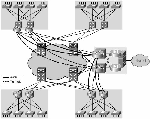
As shown in the examples, two levels of address space are involved in this setup. One is the global address space, which contains the loopback interfaces used as endpoints to create the tunnels. The other level of address space contains the addresses in the VRFs, which include the tunnel interfaces. Therefore, the 10.x.x.x network in the example is in the global table and is used to create the tunnels; the 172.16.x.x networks exist on the VRF and tunnel overlay. Note Each of these address spaces will require its own control plane. We will discuss this in the upcoming section "Resiliency and Routing Considerations." Multipoint GRE TunnelsMultipoint GRE (mGRE) tunnels provide a more scalable way of handling the aggregation of multiple GRE tunnels at a hub site. The configuration of many tunnel interfaces at the hub is replaced by a single multipoint tunnel interface. When using multiple p2p tunnels, each spoke site is associated to a tunnel, and therefore routing traffic onto the correct site is done based on tunnel interface. This is the same routing paradigm followed by a router with many physical interfaces. When you are using mGRE at the hub, the router has a single interface onto which all spoke sites are mapped. In this scenario, the routing table at the hub maps all spoke prefixes to the same interface (the multipoint tunnel). A mechanism is necessary at the hub to determine which spoke of the multipoint tunnel traffic is destined for. This mechanism could be Tunnel Endpoint Discovery (TED), Border Gateway Protocol (BGP), or the Next Hop Resolution Protocol (NHRP). Note NHRP, defined in RFC 2332, is a Layer 2 address-resolution protocol and cache, similar to Address Resolution Protocol (ARP) and Frame Relay inverse-ARP. When a tunnel interface is an mGRE, NHRP tells the mGRE process where to tunnel a packet to reach a certain address. NHRP is a client/server protocol where the hub is the server and the spokes are the clients. The hub maintains an NHRP database where it registers, for each spoke, the mapping between the physical address (used as GRE tunnel destination) and the logical address assigned to the spoke tunnel interface. Each spoke provides this information to the hub, sending an NHRP registration message at boot time. The use of an mGRE hub and NHRP is a subset of the dynamic multipoint VPN (DMVPN) architecture described in Chapter 5. A complete DMVPN implementation would also include an encryption component. However, encryption is usually not of relevance in the campus or the private MAN. This discussion does not include the encryption component of DMVPN; if required, it could be easily overlaid onto the proposed solution. The configuration steps required to create the hub-and-spoke overlay network using mGRE interfaces on the hub devices are detailed below; the configuration samples refer to the devices highlighted with a circle in the network diagram in Figure 6-7. Figure 6-7. Hub-and-Spoke Using mGRE Technology The topology, shown in Figure 6-7, consists of two headend Catalyst 6500 switches, each with an mGRE tunnel interface that connects to all the spoke routers. Every spoke is configured with two p2p GRE tunnel interfaces, each going to the respective headend. Hub mGRE ConfigurationThe main advantage of using the mGRE technology for the hub devices is the fact that only one tunnel interface (with corresponding loopback) needs to be defined. In addition, a single subnet (in this example, 172.16.100.0/24) is required to connect the hub to all the spokes eventually defined at the edge of the enterprise network. Example 6-17 shows the configuration required to create an mGRE interface on the hub and to enable the NHRP functionality. Example 6-17. mGRE hub Configuration
NHRP is enabled on the mGRE interface with the command ip nhrp network-id value, where the value specified must match the one configured on the spoke devices. In addition, the ip nhrp map multicast dynamic command is required to enable dynamic routing protocols to work over the mGRE tunnel when IGP routing protocols use multicast packets. The dynamic keyword prevents the hub router from requiring a separate configuration line for a multicast mapping for each spoke router; this is important because the goal is to avoid any reconfiguration of the hub devices when adding a new spoke component. Spoke GRE ConfigurationThe configuration of the spoke devices shown in Example 6-18 is almost identical to the one previously described for the p2p scenario; the only difference is the addition of the NHRP-related commands. Example 6-18. mGRE Spoke Configuration
Similarly to the hub case, the command ip nhrp network-id value is used to enable the NHRP process on the tunnel interfaces (the values specified must match the values configured on the two hubs). In addition to that, ip nhrp nhs needs to be added to specify the address of the NHRP server (hub). Finally, ip nhrp registration timeout seconds is required to tune the frequency (in seconds) at which the spokes send the NHRP registration messages to the hubs. This command is required to allow a spoke to reregister in case the connectivity with the hub is interrupted and restored; by default, that would happen every 2400 seconds. Note The command ip nhrp map multicast is not required on the spoke devices; the reason for this is that the tunnel interface is p2p, so all multicast packets will be automatically sent to the hub. As already discussed in the GRE p2p scenario, a mapping from the logical VLAN interface (SVI) defining the guest subnet and the guest VRF is also required. Example 6-19 shows the mapping between VRFs and SVIs. Example 6-19. Mapping Subnets to VRFs
Mapping Traffic to TunnelsTo create an end-to-end group, traffic from the access VLANs must be mapped to the different logical tunnel overlays. This mapping can be achieved based on IP policies with PBR or based on the traffic source with VRFs. The next sections describe how to achieve this mapping. PBRYou can use PBR to force traffic over a specific interface or toward a specific next hop. When using PBR to steer traffic into a GRE tunnel, you can take one of two approaches:
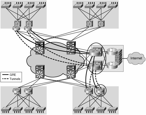
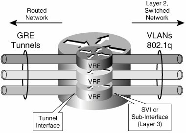
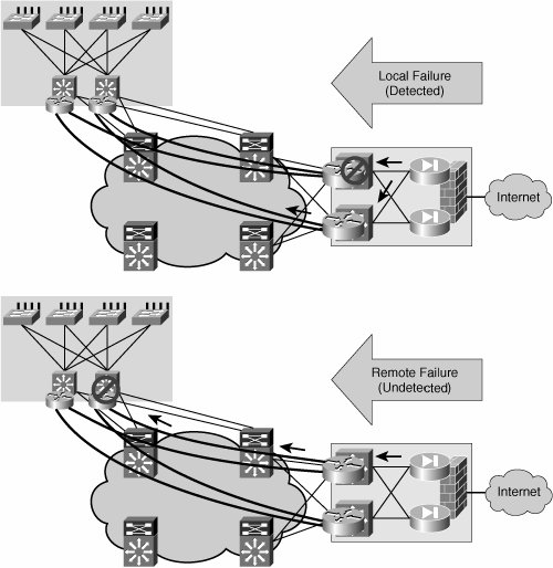
In either case, the decision to act upon traffic will be based on an IP policy. Therefore, the challenges involved with using PBR to steer traffic into a mesh of tunnels are similar to the scaling challenges faced when using distributed ACLs in a campus network or MAN. A more flexible and scalable solution is provided by VRFs. VRFsVRFs allow the creation of independent routing spaces. The tunnel interfaces in the overlay can be made part of the separate routing space created by a VRF. When the tunnel interfaces are part of a VRF routing space, they are also included in the routing table as a valid path to reach certain prefixes. Therefore, if the tunnel interfaces are the preferred route to reach subnets in the remote VRFs, steering traffic into the tunnels is a matter of simple IP forwarding. It is important to clarify that only traffic that has been assigned to a VRF will eventually make it into the tunnels. The steering of traffic into the tunnels starts with the assignment of traffic to a VLAN or interface that is bound to a VRF. This traffic will eventually use the tunnels because these should be the preferred interfaces for reaching the remote VRFs and their associated subnets. Figure 6-8 illustrates the associations between VLANs, ports, VRFs, and finally tunnels that achieve the mapping of traffic to a tunnel mesh. Figure 6-8. Traffic Mapping Between VLANs, VRFs, and Tunnels Resiliency and Routing ConsiderationsThe enterprise campus network is characterized by an abundance of resilient high bandwidth links. The same can be said about certain portions of the MAN. The possibility of deploying multiple links drives a highly resilient network design that involves having multiple devices (usually two) connecting each subnet to the routed core. This resilient connection of a subnet to the core is often referred to as multihoming. When overlaying a logical tunnel mesh to such an environment, it will be necessary to deploy multiple tunnels per site to preserve the resiliency provided by the multihomed array. For the purposes of this discussion, we examine the scenario in which there are dual distribution switches per site (or distribution block) and, therefore, there are dual tunnels connecting each distribution router to the headend at the hub distribution block. Figure 6-9 illustrates the tunnel mesh required to support a resilient distribution. Figure 6-9. Resilient GRE Tunnel Overlay Equal-cost routes to the destination network via the redundant tunnels will help load balance traffic over the two tunnels. These routes could either be learned dynamically from a routing protocol or statically configured. Note The GRE header hides the flow information in all packets. Even if a network is enabled with equal-cost paths for load balancing, traffic sent over a single GRE tunnel will always follow the same path and therefore not be load balanced. Traffic is best load balanced per flow and not per packet to avoid out of sequence packet reception. As the GRE header encapsulates (hides) the flow information, the routers cannot properly determine which packets belong to which flow to load balance the flows. Nevertheless, the flows can be identified before entering any tunnel, and load balancing can happen over multiple tunnels. In principle, the core of the network should be able to recuperate from a failure in the core without a need for multiple tunnels. The IP network should reconverge and provide an alternate path for the original tunnel to continue forwarding traffic. This is true for failures that occur inside the core. However, this is not the case when the failure occurs at the tunnel endpoints (campus network distribution) or beyond the endpoints (access-distribution uplinks). If a distribution switch fails, or if any of the uplinks from the access switches fail, the redundant distribution switch should take over and continue to forward traffic upstream and downstream. The failover is straightforward for traffic originated at the failed site. Regular spanning-tree and first-hop resiliency mechanisms such as HSRP will ensure that traffic is diverted around a local failure. The multiple tunnels will be active at all times, providing a path for the traffic being sent regardless of the failover state of the distribution block. Failover of traffic received at a failed distribution block is slightly more involved. For this scenario, the local "healthy" distribution block would need to send traffic only over the tunnels that terminate on the remaining "healthy" switch at the remote failed distribution block. Figure 6-10 illustrates local and remote failure scenarios. Figure 6-10. Local and Remote Failures One important consideration to make when working with GRE tunnels is that these do not have a keepalive mechanism. This means that if one end of the tunnel goes down, the other end will not be informed of this failure and will continue to forward traffic over the failed tunnel, which will result in "blackholed" traffic. This is exactly the situation encountered in the remote failure scenario described earlier and illustrated in Figure 6-10. Deploying a dynamic routing protocol that peers over the tunnels is one way of providing a mechanism for dynamic tunnel failure detection (other mechanisms such as GRE tunnel keepalives are available in specific platforms). The routing entry for a prefix reachable over a failed tunnel should age out as the advertising neighbor is lost. Traffic should no longer be forwarded over the failed tunnel interface, forcing all traffic over the remaining healthy tunnel. Thus, a dynamic routing protocol provides both load-balancing information and remote failure signaling. It is therefore critical to enable a routing protocol over the GRE tunnel mesh. This is easily done when using VRFs to map traffic to tunnels. It becomes a bit more involved when using PBR to steer traffic into the tunnel mesh, requiring tracking mechanisms and detailed route filtering. We will now analyze these two scenarios. Figure 6-11 shows VRFs mapped to a redundant mesh of tunnels between two redundant distribution blocks. To provide remote failure detection, an IGP is enabled on the VRFs, and IGP peering is established over the tunnels. When traffic is forwarded by the distribution switch, a tunnel is chosen based on the information in the VRF (routing table). Because the VRF is updated dynamically by the IGP, it will only contain healthy routes. Therefore, if a prefix is not reachable over a specific tunnel, this route will not be listed in the VRF as a valid alternative and no traffic will be forwarded over this tunnel. Figure 6-11. IGP on VRFs for Dynamic Tunnel Failure Detection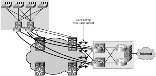 When no VRFs are present and traffic is steered into the tunnels by means of PBR, a dynamic routing protocol will be of little help in choosing a healthy tunnel to forward traffic. PBR will steer traffic into the failed tunnel regardless of the state of the routing protocol; in this respect, it is equivalent to having static routes that override any dynamically learned routes. Therefore, it is necessary to provide conditional PBR functionality, which means the static PBR routes will only be enforced if the routes are feasible (that is, if the tunnel is healthy and the routes are learned over the tunnel). Therefore, to achieve resiliency when using PBR to steer traffic into the tunnels, two components are necessary:
Without the dynamic routing protocol, the conditional PBR functionality has no way of determining whether the tunnel is healthy. Hence, both elements are required. Note It is important to highlight that we have proposed using either PBR or VRFs to steer traffic into the tunnel mesh, but not a combination of them. In the current implementation, PBR and VRFs do not interoperate. Regardless of the technique used to steer traffic into the tunnels, a routing protocol must be overlaid to the tunnel mesh. Certain considerations must be made for the deployment of an IGP over GRE tunnels, including the following:
Based on these considerations, the configuration of the generic hub-and-spoke GRE interfaces would need to be changed as shown in Example 6-20 (configuration excerpt valid for OSPF). Example 6-20. Enabling OSPF on a Hub-and-Spoke mGRE Overlay
The hub devices will learn all the routes for the spoke subnets out of the same mGRE interface. The additional information contained in the NHRP cache allows the hubs to be able to route back the traffic to the proper spokes. Example 6-21 shows command-line interface (CLI) output valid for an EIGRP example. Note Notice how every prefix is reachable over the same tunnel 0 interface, but via different next-hop routers. Example 6-21. Hub Routes in a Hub-and-Spoke mGRE Overlay
Encryption ConsiderationsEncryption of the tunnel overlay is rarely a requirement in a campus or MAN environment. Chapter 5 "Infrastructure Segmentation Architectures: Theory" discussed how to enable encryption over a GRE tunnel. Should there be an encryption requirement, the same principles would apply to the logical overlays described in this section. We study encryption in much more detail in Chapter 7 "Extending the Virtualized Enterprise over the WAN." |
EAN: 2147483647
Pages: 128