Central Services Access: Virtual Network Perimeter
| The default state of a VN is to be totally isolated from other VNs. In this respect, VNs could be seen as physically separate networks. However, because VNs actually belong to a common physical network, it is desirable for these VNs to share certain services such as Internet access, management stations, DHCP services, Domain Name System (DNS) services, or server farms. These services will usually be located outside of the different VNs or in a VN of their own. So, it is necessary for these VNs to have a gateway to connect to the "outside world." The outside world is basically any network outside the VN such as the Internet or other VNs. Because this is the perimeter of the VN, it is also desirable for this perimeter to be protected by security devices such as firewalls and intrusion detection systems (IDSs). Typically, the perimeter is deployed at a common physical location for most VNs. Hence, this location is known as the central services site, and the security devices here deployed can be shared by many VNs. The creation of VNs could be seen as the creation of security zones, each of which has a unique and controlled entry/exit point at the VN perimeter. Routing within the VNs should be configured so that traffic is steered to the common services site as required. Figure 3-8 illustrates a typical perimeter deployment for multiple VNs accessing common services. Because the services accessed through the VN perimeter are protected by firewalls, we refer to these as "protected services." Figure 3-8. Central Site Providing VN Perimeter Security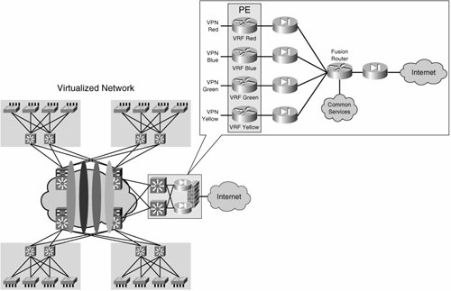 As shown in Figure 3-8, each VN is head ended by a dedicated firewall. This allows the creation of security policies specific to each VN and independent from each other. To access the shared services, all firewalls are connected to a "fusion" router. The fusion router can provide the VNs with connectivity to the common services, the Internet, or even inter-VN connectivity. The presence of this fusion router should raise two main concerns:
The presence of dedicated per-VN firewalls prevents the leaking of traffic between VNs through the fusion router by only allowing established connections (connections initiated from "inside" the firewall) to return through the VN perimeter. It is key to configure the routing on the fusion device so that routes from one VN are not advertised to another through the fusion router. The details of the routing configuration at the central site are discussed in Chapter 8, "Traffic Steering and Service Centralization." Figure 3-8 shows an additional firewall separating the fusion area from the Internet. This firewall is optional. Whether to use it or not depends on the need to keep common services or transit traffic in the fusion area protected from the Internet. As mentioned, the common services could exist in a central location or in their own VN and therefore distributed throughout the enterprise. Depending on where the common services are located, the VN perimeter topology will vary. Figure 3-9 illustrates the different scenarios for common services positioning and the Internet firewall. Figure 3-9. Common Services Positioning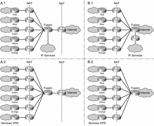 When the common services are not present, or are placed in their own VN (and therefore front-ended by a dedicated firewall context) the additional Internet firewall can be removed, as shown in scenario B.2 of Figure 3-9. If concern exists about transit traffic (between VNs or between a VN and the shared services area) being on the Internet, the firewall can be kept (see diagram A.2). The common services could be separated from the rest of the network by having their own firewall, yet not be included in a VN; this is shown in scenario B.1 in Figure 3-9. For scenarios B.1 and B.2 in Figure 3-9, it is important to note that the fusion router is actually part of the Internet; therefore the Network Address Translation (NAT) pool used at the firewalls must use valid Internet addresses. The deployment of the optional Internet firewall should follow standard Internet edge design guidance, which has been extensively documented across networking literature. The reference designs proposed by Cisco and published at http://www.cisco.com/go/srnd are good sources of information. The "Data Center: Internet Edge Design" document contains a comprehensive discussion on the topic. We use scenario A.1 from Figure 3-9 to illustrate the relevant design and deployment considerations, but these considerations are applicable to other scenarios. Unprotected ServicesIn contrast with circuit-based technologies such as ATM or Frame Relay, most Layer 3 VPN technologies allow enough flexibility for traffic to be leaked between VNs in a controlled manner by importing and exporting routes between VNs to provide IP connectivity between the VNs. Thus, the exchange of traffic between the VNs may happen within the IP core and not have to pass through the VN perimeter firewalls at the central site. This type of inter-VN connectivity can be used to provide services, such as DHCP or DNS, that do not need to be protected by the central site firewall, or that would represent an unnecessary burden to the VN perimeter firewalls. Because of the any-to-any nature of an IP cloud, there is little chance of controlling inter-VN traffic after the routes have been exchanged. We refer to these as "unprotected services." This type of connectivity must be deployed carefully because it can potentially create unwanted back doors between VNs and break the concept of the VN as a "security zone" protected by a robust VN perimeter front end. Another consideration that must be made is the fact that importing and exporting routes between VNs precludes the use of overlapping address spaces between the VNs. We discuss the use of route-importing mechanisms for the creation of common services extranet VNs in detail in Chapter 8. Note Although, these services are not protected by the VN perimeter firewalls, the IP segment to which they belong could potentially be head-ended by a firewall and therefore "protected." The deployment of protected services does not preclude the deployment of unprotected services and vice versa. In a virtualized network, a combination of protected and unprotected services is usually provided for the different VNs. For example, the DHCP and DNS services for several VNs may be shared and accessed in an unprotected manner, while all server farms and the Internet are also shared among the different VNs, but their access must be controlled by firewall policies and an IDS. |
EAN: 2147483647
Pages: 128
- Article 340 Underground Feeder and Branch-Circuit Cable Type UF
- Article 360 Flexible Metallic Tubing Type FMT
- Article 424: Fixed Electric Space Heating Equipment
- Example No. D8 Motor Circuit Conductors, Overload Protection, and Short-Circuit and Ground-Fault Protection
- Example No. D10 Feeder Ampacity Determination for Adjustable-Speed Drive Control [See 215.2, 430.24, 620.13, 620.14, 620.61, Tables 430.22(E), and 620.14]