Section 7.1. Network Concepts
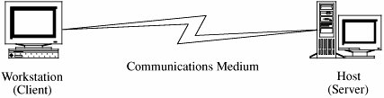
7.1. Network ConceptsTo study network threats and controls, we first must review some of the relevant networking terms and concepts. This review does not attempt to provide the depth of a classic networking reference, such as [COM04, STE02, GAL99, or TAN03]. In earlier chapters, our study of security focused on the individual pieces of a computing system, such as a single application, an operating system, or a database. Networks involve not only the pieces but alsoimportantlythe connections among them. Networks are both fragile and strong. To see why, think about the power, cable television, telephone, or water network that serves your home. If a falling tree branch breaks the power line to your home, you are without electricity until that line is repaired; you are vulnerable to what is called a single point of failure, because one cut to the network destroys electrical functionality for your entire home. Similarly, there may be one telephone trunk line or water main that serves your home and those nearby; a failure can leave your building, street, or neighborhood without service. But we have ways to keep the entire network from failing. If we trace back through the network from your home to the source of what flows through it, we are likely to see that several main distribution lines support an entire city or campus. That is, there is more than one way to get from the source to your neighborhood, enabling engineers to redirect the flow along alternative paths. Redundancy makes it uncommon for an entire city to lose service from a single failure. For this reason, we say that such a network has resilience or fault tolerance. Complex routing algorithms reroute the flow not just around failures but also around overloaded segments. The routing is usually done automatically; the control program is often supplemented by human supervision or intervention. Many types of networks have very high reliability by design, not by accident. But because there often is less redundancy near a network's endpoints than elsewhere, we say that the network has great strength in the middle and fragility at the perimeter. From the user's perspective, a network is sometimes designed so that it looks like two endpoints with a single connection in the middle. For example, the municipal water supply may appear to be little more than a reservoir (the source), the pipes (the transmission or communication medium), and your water faucet (the destination). Although this simplistic view is functionally correct, it ignores the complex design, implementation, and management of the "pipes." In a similar way, we describe computer networks in this chapter in ways that focus on the security concepts but present the networks themselves in a simplistic way, to highlight the role of security and prevent the complexity of the networks from distracting our attention. Please keep in mind that our network descriptions are often abstractions of a more complex actuality. The NetworkFigure 7-1 shows a network in its simplest form, as two devices connected across some medium by hardware and software that enable the communication. In some cases, one device is a computer (sometimes called a "server") and the other is a simpler device (sometimes called a "client") enabled only with some means of input (such as a keyboard) and some means of output (such as a screen). For example, a powerful computer can be a server, but a handheld personal digital assistant (PDA) or a cell phone might be a network client. In fact, because more consumer devices are becoming network-enabled, network security issues will continue to grow. Figure 7-1. Simple View of Network. Although this model defines a basic network, the actual situation is frequently significantly more complicated.
Most real-world situations are more like Figure 7-2. In this second view, the user at one of the lettered client machines may send a message to System 3, unaware that communication is actually passing through the active Systems 1 and 2. In fact, the user may be unaware that System 3 sometimes passes work to System 4. A single computing system in a network is often called a node, and its processor (computer) is called a host. A connection between two hosts is known as a link. Network computing consists of users, communications media, visible hosts, and systems not generally visible to end users. In Figure 7-2, Systems 1 through 4 are nodes. In our figure the users are at the lettered client machines, perhaps interacting with Server F. Users communicate with networked systems by interacting directly with terminals, workstations, and computers. A workstation is an end-user computing device, usually designed for a single user at a time. Workstations often have powerful processors and good-sized memory and storage so that they can do sophisticated data manipulation (such as converting coded data to a graphical format and displaying the picture). A system is a collection of processors, perhaps including a mixture of workstations and independent processors, typically with more processing power and more storage capacity than a workstation. Environment of UseThe biggest difference between a network and a stand-alone device is the environment in which each operates. Although some networks are located in protected spaces (for example, a local area network in a single laboratory or office), at least some portion of most networks is exposed, often to total strangers. The relatively simple network in Figure 7-2 is a good example. Systems 2, 3, and 4 are remote from System 1, and they may be under different ownership or control. Figure 7-2. More Complex but More Typical View of Networks.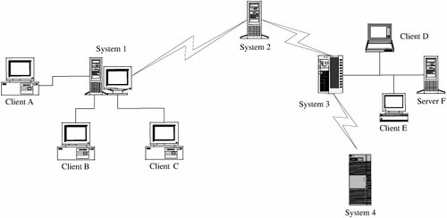 Networks can be described by several typical characteristics:
Shape and SizeThe way a network is configured, in terms of nodes and connections, is called the network topology. You can think of the topology as the shape of the network. The topology ranges from very simple, such as two hosts connected by one path, to very complex, such as the Internet. These two extremes highlight three dimensions of networks that have particular bearing on a network's security.
The truth is that, for many networks, it is difficult and at times impossible to tell which hosts are part of that network, who owns the hosts, and who controls them. Even for networks significantly smaller than the Internet, major corporate, university, or government networks are hard to understand and are not even well known by their system administrators. Although it seems contrary to common sense, many corporations today have no accurate picture of how their networks are configured. To understand why, consider a network of automated teller machines for a multinational bank. The bank may have agreements with other banks to enable customers to withdraw money anywhere in the world. The multinational bank may understand its own bank's network, but it may have no conception of how the connecting banks' networks are configured; no "big picture" shows how the combined networks look or operate. Similarly, a given host may be part of more than one network. In such a situation, suppose a host has two network interfaces. Whose rules does that host (and that host's administrator) have to follow? Depicting, configuring, and administering networks are not easy tasks. Mode of CommunicationA computer network implements communication between two endpoints. Data are communicated either in digital format (in which data items are expressed as discrete binary values) or analog (in which data items are expressed as points in a continuous range, using a medium like sound or electrical voltage). Computers typically store and process digital data, but some telephone and similar cable communications are in analog form (because telephones were originally designed to transmit voice). When the transmission medium expects to transfer analog data, the digital signals must be converted to analog for transmission and then back to digital for computation at the receiving end. Some mostly analog networks may even have some digital segments, so the analog signals are digitized more than once. These conversions are performed by a modem (the term is derived from modulator-demodulator), which converts a digital data stream to tones and back again. MediaCommunication is enabled by several kinds of media. We can choose among several types, such as along copper wires or optical fiber or through the air, as with cellular phones. Let us look at each type in turn. CableBecause much of our computer communication has historically been done over telephone lines, the most common network communication medium today is wire. Inside our homes and offices, we use a pair of insulated copper wires, called a twisted pair or unshielded twisted pair (UTP). Copper has good transmission properties at a relatively low cost. The bandwidth of UTP is limited to under 10 megabits per second (Mbps),[1] so engineers cannot transmit a large number of communications simultaneously on a single line. Moreover, the signal strength degrades as it travels through the copper wire, and it cannot travel long distances without a boost. Thus, for many networks, line lengths are limited to approximately 300 feet. Single twisted pair service is most often used locally, within a building or up to a local communications drop (that is, the point where the home or office service is connected to the larger network, such as the commercial telephone system). Although regular copper wire can transmit signals, the twisting reduces crossover (interference and signal transfer) between adjacent wires.
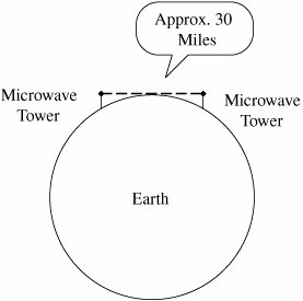
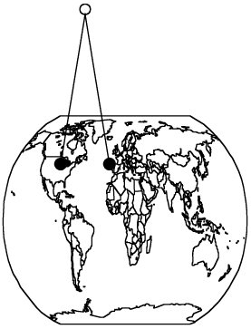
Another choice for network communication is coaxial (coax) cable, the kind used for cable television. Coax cable is constructed with a single wire surrounded by an insulation jacket. The jacket is itself surrounded by a braided or spiral-wound wire. The inner wire carries the signal, and the outer braid acts as a ground. The most widely used computer communication coax cable is Ethernet, carrying up to 100 Mbps over distances of up to 1500 feet. Coax cable also suffers from degradation of signal quality over distance. Repeaters (for digital signals) or amplifiers (for analog signals) can be spaced periodically along the cable to pick up the signal, amplify it, remove spurious signals called "noise," and retransmit it. Optical FiberA newer form of cable is made of very thin strands of glass. Instead of carrying electrical energy, these fibers carry pulses of light. The bandwidth of optical fiber is up to 1000 Mbps, and the signal degrades less over fiber than over wire or coax; the fiber is good for a run of approximately 2.5 miles. Optical fiber involves less interference, less crossover between adjacent media, lower cost, and less weight than copper. Thus, optical fiber is generally a much better transmission medium than copper. Consequently, as copper ages, it is being replaced by optical fiber in most communication systems. In particular, most long distance communication lines are now fiber. WirelessRadio signals can also carry communications. Similar to pagers, wireless microphones, garage door openers, and portable telephones, wireless radio can be used in networks, following a protocol developed for short-range telecommunications, designated the 802.11 family of standards. The wireless medium is used for short distances; it is especially useful for networks in which the nodes are physically close together, such as in an office building or at home. Many 802.11 devices are becoming available for home and office wireless networks. MicrowaveMicrowave is a form of radio transmission especially well suited for outdoor communication. Microwave has a channel capacity similar to coax cable; that is, it carries similar amounts of data. Its principal advantage is that the signal is strong from point of transmission to point of receipt. Therefore, microwave signals do not need to be regenerated with repeaters, as do signals on cable. However, a microwave signal travels in a straight line, presenting a problem because the earth curves. Microwave signals travel by line of sight: The transmitter and receiver must be in a straight line with one another, with no intervening obstacles, such as mountains. As shown in Figure 7-3, a straight microwave signal transmitted between towers of reasonable height can travel a distance of only about 30 miles because of the earth's curvature. Thus, microwave signals are "bounced" from receiver to receiver, spaced less than 30 miles apart, to cover a longer distance. InfraredInfrared communication carries signals for short distances (up to 9 miles) and also requires a clear line of sight. Because it does not require cabling, it is convenient for portable objects, such as laptop computers and connections to peripherals. An infrared signal is difficult to intercept because it is a point-to-point signal. However, it is subject to "in the middle" attacks in which the interceptor functions like a repeater, receiving the signal, extracting any desired data, and retransmitting to the original destination the original signal or a modified version. Because of line-of-sight requirements and limited distance, infrared is typically used in a protected space, such as an office, in which in-the-middle attacks would be difficult to conceal. Figure 7-3. Microwave Transmission. SatelliteMany communications, such as international telephone calls, must travel around the earth. In the early days of telephone technology, telephone companies ran huge cables along the ocean's bottom, enabling calls to travel from one continent to another. Today, we have other alternatives. The communication companies place satellites in orbits that are synchronized with the rotation of the earth (called geosynchronous orbits), so the satellite appears to hover in a fixed position 22,300 miles above the earth. Although the satellite can be expensive to launch, once in space it is essentially maintenance free. Furthermore, the quality of a satellite communication link is often better than an earthbound wire cable. Satellites act as naïve transponders: Whatever they receive they broadcast out again. Thus, satellites are really sophisticated receivers, in that their sole function is to receive and repeat signals. From the user's point of view, the signal essentially "bounces" off the satellite and back to earth. For example, a signal from North America travels 22,300 miles into the sky and the same distance back to a point in Europe. The process of bouncing a signal off a satellite is shown in Figure 7-4. We can project a signal to a satellite with reasonable accuracy, but the satellite is not expected to have the same level of accuracy when it sends the signal back to earth. To reduce complexity and eliminate beam focusing, satellites typically spread their transmissions over a very wide area. A rather narrow angle of dispersion from the satellite's transmitter produces a fairly broad pattern (called the footprint) on the surface of the earth because of the 22,300-mile distance from the satellite to earth. Thus, a typical satellite transmission can be received over a path several hundred miles wide; some cover the width of the entire continental United States in a single transmission. For some applications, such as satellite television, a broad footprint is desirable. But for secure communications, the smaller the footprint, the less the risk of interception. Figure 7-4. Satellite Communication. ProtocolsWhen we use a network, the communication media are usually transparent to us. That is, most of us do not know whether our communication is carried over copper wire, optical fiber, satellite, microwave, or some combination. In fact, the communication medium may change from one transmission to the next. This ambiguity is actually a positive feature of a network: its independence. That is, the communication is separated from the actual medium of communication. Independence is possible because we have defined protocols that allow a user to view the network at a high, abstract level of communication (viewing it in terms of user and data); the details of how the communication is accomplished are hidden within software and hardware at both ends. The software and hardware enable us to implement a network according to a protocol stack, a layered architecture for communications. Each layer in the stack is much like a language for communicating information relevant at that layer. Two popular protocol stacks are used frequently for implementing networks: the Open Systems Interconnection (OSI) and the Transmission Control Protocol and Internet Protocol (TCP/IP) architecture. We examine each one in turn. ISO OSI Reference ModelThe International Standards Organization (ISO) Open Systems Interconnection model consists of layers by which a network communication occurs. The OSI reference model contains the seven layers listed in Table 7-1.
How communication works across the different layers is depicted in Figure 7-5. We can think of the layers as creating an assembly line, in which each layer adds its own service to the communication. In concert, the layers represent the different activities that must be performed for actual transmission of a message. Separately, each layer serves a purpose; equivalent layers perform similar functions for the sender and receiver. For example, the sender's layer four affixes a header to a message, designating the sender, the receiver, and relevant sequence information. On the receiving end, layer four reads the header to verify that the message is for the intended recipient, and then removes this header. Figure 7-5. ISO OSI Network Model.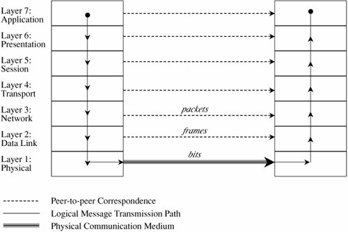 Each layer passes data in three directions: above with a layer communicating more abstractly, parallel or across to the same layer in another host, and below with a layer handling less abstract (that is, more fundamental) data items. The communications above and below are actual interactions, while the parallel one is a virtual communication path. Parallel layers are called "peers." Let us look at a simple example of protocol transmission. Suppose that, to send email to a friend, you run an application such as Eudora, Outlook, or Unix mail. You type a message, using the application's editor, and the application formats the message into two parts: a header that shows to whom the message is intended (as well as other things, such as sender and time sent), and a body that contains the text of your message. The application reformats your message into a standard format so that even if you and your friend use different mail applications, you can still exchange e-mail. This transformation is shown in Figure 7-6. Figure 7-6. Transformation. However, the message is not transmitted exactly as you typed it, as raw text. Raw text is a very inefficient coding, because an alphabet uses relatively few of the 255 possible characters for an 8-bit byte. Instead, the presentation layer is likely to change the raw text into something else. It may do compression, character conversions, and even some cryptography. An e-mail message is a one-way transfer (from sender to receiver), so it is not initiating a session in which data fly back and forth between the two endpoints. Because the notion of a communication session is not directly relevant in this scenario, we ignore the session layer for now. Occasionally, spurious signals intrude in a communication channel, as when static rustles a telephone line or interference intrudes on a radio or television signal. To address this, the transport layer adds error detection and correction coding to filter out these spurious signals. AddressingSuppose your message is addressed to yourfriend@somewhere.net. This notation means that "somewhere.net" is the name of a destination host (or more accurately, a destination network). At the network layer, a hardware device called a router actually sends the message from your network to a router on the network somewhere.net. The network layer adds two headers to show your computer's address as the source and somewhere.net's address as the destination. Logically, your message is prepared to move from your machine to your router to your friend's router to your friend's computer. (In fact, between the two routers there may be many other routers in a path through the networks from you to your friend.) Together, the network layer structured with destination address, source address, and data is called a packet. The basic network layer protocol transformation is shown in Figure 7-7. Figure 7-7. Network Layer Transformation.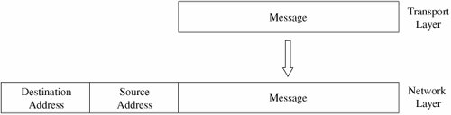 The message must travel from your computer to your router. Every computer connected to a network has a network interface card (NIC) with a unique physical address, called a MAC address (for Media Access Control). At the data link level, two more headers are added, one for your computer's NIC address (the source MAC) and one for your router's NIC address. A data link layer structure with destination MAC, source MAC, and data is called a frame. Every NIC selects from the network those frames with its own address as a destination address. As shown in Figure 7-8, the data link layer adds the structure necessary for data to get from your computer to another computer (a router is just a dedicated computer) on your network. Figure 7-8. Data Link Layer Transformation.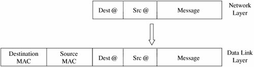 Finally, the message is ready to be sent out as a string of bits. We noted earlier that analog transmissions communicate bits by using voltage or tone changes, and digital transmissions communicate them as discrete pulses. The physics and electronics of how bits are actually sent are handled at the physical layer. On the receiving (destination) side, this process is exercised in reverse: Analog or digital signals are converted to digital data. The NIC card receives frames destined for it. The recipient network layer checks that the packet is really addressed to it. Packets may not arrive in the order in which they were sent (because of network delays or differences in paths through the network), so the session layer may have to reorder packets. The presentation layer removes compression and sets the appearance appropriate for the destination computer. Finally, the application layer formats and delivers the data as an e-mail message to your friend. The layering and coordinating are a lot of work, and each protocol layer does its own part. But the work is worth the effort because the different layers are what enable Outlook running on an IBM PC on an Ethernet network in Washington D.C. to communicate with a user running Eudora on an Apple computer via a dial-up connection in Prague. Moreover, the separation by layers helps the network staff troubleshoot when something goes awry. LayeringEach layer reformats the transmissions and exchanges information with its peer layer. Let us summarize what each layer contributes. Figure 7-9 shows a typical message that has been acted upon by the seven layers in preparation for transmission. Layer 6 breaks the original message data into blocks. At the session layer (5), a session header is added to show the sender, the receiver, and some sequencing information. Layer 4 adds information concerning the logical connection between the sender and receiver. The network layer (3) adds routing information and divides the message into units called packets, the standard units of communication in a network. The data link layer (2) adds both a header and a trailer to ensure correct sequencing of the message blocks and to detect and correct transmission errors. The individual bits of the message and the control information are transmitted on the physical medium by level 1. All additions to the message are checked and removed by the corresponding layer on the receiving side. Figure 7-9. Message Prepared for Transmission.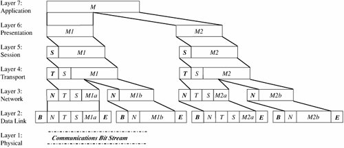 The OSI model is one of several transmission models. Different network designers implement network activities in slightly different combinations, although there is always a clear delineation of responsibility. Some designers argue that the OSI model is overly complexit has too many levelsand so other models are typically shorter. TCP/IPThe OSI model is a conceptual one; it shows the different activities required for sending a communication. However, full implementation of a seven-layer transmission carries too much overhead for megabit-per-second communications; the OSI protocol slows things down to unacceptable levels. For this reason, TCP/IP (Transmission Control Protocol/Internet Protocol) is the protocol stack used for most wide area network communications. TCP/IP was invented for what became the Internet. TCP/IP is defined by protocols, not layers, but we can think of it in terms of four layers: application, host-to-host (end-to-end) transport, Internet, and physical. In particular, an application program deals only with abstract data items meaningful to the application user. Although TCP/IP is often used as a single acronym, it really denotes two different protocols: TCP implements a connected communications session on top of the more basic IP transport protocol. In fact, a third protocol, UDP (user datagram protocol) is also an essential part of the suite. The transport layer receives variable-length messages from the application layer; the transport layer breaks them down into units of manageable size, transferred in packets. The Internet layer transmits application layer packets in datagrams, passing them to different physical connections based on the data's destination (provided in an address accompanying the data). The physical layer consists of device drivers to perform the actual bit-by-bit data communication. Table 7-2 shows how each layer contributes to the complete interaction.
The TCP protocol must ensure the correct sequencing of packets as well as the integrity (correct transmission) of data within packets. The protocol will put out-of-sequence packets in proper order, call for retransmitting a missing packet, and obtain a fresh copy of a damaged packet. In this way, TCP hands a stream of correct data in proper order to the invoking application. But this service comes at a price. Recording and checking sequence numbers, verifying integrity checks, and requesting and waiting for retransmissions of faulty or missing packets take time and induce overhead. Most applications expect a flawless stream of bits, but some applications can tolerate a less accurate stream of data if speed or efficiency is critical. A TCP packet is a data structure that includes a sequence number, an acknowledgment number for connecting the packets of a communication session, flags, and source and destination port numbers. A port is a number designating a particular application running on a computer. For example, if Jose and Walter begin a communication, they establish a unique channel number by which their computers can route their respective packets to each of them. The channel number is called a port. Each service uses a well-known port, such as port 80 for HTTP (web pages), 23 for Telnet (remote terminal connection), 25 for SMTP (e-mail), or 161 for SNMP (network management). More precisely, each of these services has a waiting process that monitors the specified port number and tries to perform its service on any data passed to the port. The UDP protocol does not provide the error-checking and correcting features of TCP, but it is a much smaller, faster protocol. For instance, a UDP datagram adds 8 bytes for control information, whereas the more complex TCP packet adds at least 24 bytes. Most applications do not interact directly in TCP or UDP themselves. Instead, they operate on data structured by an application-level protocol applied on top of TCP or UDP. Some of the more common Internet protocols are shown in Table 7-3.
Whatever the model, a layer will typically subdivide data it receives from a higher layer and then add header and/or trailer information to the data before passing it to a lower layer. Each layer encapsulates the higher layer, so that higher layer headers and trailers are seen simply as part of the data to be transmitted. Addressing SchemeFor communication to occur, the bits have to be directed to somewhere. All networks use an addressing scheme so that data can be directed to the expected recipient. Because it is the most common, we use the Internet addressing scheme known as IP addresses in our examples, since it is the addressing handled by the IP protocol. All network models implement an addressing scheme. An address is a unique identifier for a single point in the network. For obvious reasons, addressing in shared, wide area networks follows established rules, while addressing in local area networks is less constrained. Starting at the local area network, each node has a unique address, defined in hardware on the network connector device (such as a network interface card) or its software driver. A network administrator may choose network addresses to be easy to work with, such as 1001, 1002, 1003 for nodes on one LAN, and 2001, 2002, and so forth on another. A host on a TCP/IP wide area network has a 32-bit address,[2] called an IP address. An IP address is expressed as four 8-bit groups in decimal notation, separated by periods, such as 100.24.48.6. People prefer speaking in words or pseudowords, so network addresses are also known by domain names, such as ATT.COM or CAM.AC.UK. Addressing tables convert domain names to IP addresses.
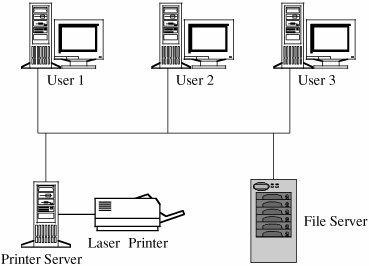
A domain name is parsed from right to left. The rightmost portion, such as .COM, .EDU, .NET, .ORG, or .GOV, or one of the two-letter country specific codes, such as .UK, .FR, .JP, or .DE, is called a top-level domain. A small set of organizations called the Internet Registrars controls these top-level domains; the registrars also control the registration of second-level domains, such as ATT in ATT.COM. Essentially, the registrars publish addresses of hosts that maintain tables of the second-level domains contained in the top-level domain. A host connected to the Internet queries one of these tables to find the numeric IP address of ATT in the .COM domain. AT&T, the company owning the ATT Internet site, must maintain its own host to resolve addresses within its own domain, such as MAIL.ATT.COM. You may find that the first time you try to resolve a fully qualified domain name to its IP address, your system performs a lookup starting at the top; for subsequent attempts, your system maintains a cache of domain name records that lets it resolve addresses locally. Finally, a domain name is translated into a 32-bit, four-octet address, and that address is included in the IP packets destined for that address. (We return to name resolution later in this chapter because it can be used in network attacks.) Routing ConceptsA host needs to know how to direct a packet from its own IP address. Each host knows to what other hosts it is directly connected, and hosts communicate their connections to their neighbors. For the example network of Figure 7-2, System 1 would inform System 2 that it was one hop away from Clients A, B, and C. In turn, System 2 would inform its other neighbor, System 3, that it (System 2) was two hops away from Clients A, B, and C. From System 3, System 2 would learn that System 3 was one hop away from Clients D and E, Server F, and System 4, which System 2 would then pass to System 1 as being a distance of two hops. The routing protocols are actually more complex than this description, but the concepts are the same; hosts advertise to their neighbors to describe to which hosts (addresses) they can route traffic and at what cost (number of hops). Each host routes traffic to a neighbor that offers a path at the cheapest cost. Types of NetworksA network is a collection of communicating hosts. But to understand the network and how it works, we have several key questions to ask, such as How many hosts? Communicating by what means? To answer these questions, we are helped by an understanding of several types of subclasses of networks, since they commonly combine into larger networks. The subclasses are general notions, not definitive distinctions. But since the terms are commonly used, we present several common network subclasses that have significant security properties. Local Area NetworksAs the name implies, a local area network (or LAN) covers a small distance, typically within a single building. Usually a LAN connects several small computers, such as personal computers, as well as printers and perhaps some dedicated file storage devices. Figure 7-10 shows the arrangement of a typical LAN. The primary advantage of a LAN is the opportunity for its users to share data and programs and to share access to devices such as printers. Figure 7-10. Typical LAN. Most LANs have the following characteristics.
Wide Area NetworksA wide area network, or WAN, differs from a local area network in terms of both size or distance (as its name implies, it covers a wider geographic area than does a LAN) and control or ownership (it is more likely not to be owned or controlled by a single body). Still, there tends to be some unifying principle to a WAN. The hosts on a WAN may all belong to a company with many offices, perhaps even in different cities or countries, or they may be a cluster of independent organizations within a few miles of each other, who share the cost of networking hardware. These examples also show how WANs themselves differ. Some are under close control and maintain a high degree of logical and physical isolation (typically, these are WANs controlled by one organization), while others are only marriages of convenience. Typical characteristics of WANs are these.
Other network types include campus area networks (CANs) and metropolitan area networks (MANs). A CAN is usually under the control of a single organization, such as a university or company, and covers the adjacent buildings of one site of that organization. A MAN often covers a city, with the communication offering of one provider in that area. CANs, MANs, and WANs cover a wide range of possibilities; they loosely characterize everything between LANs and Internets, the two extremes of the networking spectrum. Internetworks (Internets)Networks of networks, or internetwork networks, are sometimes called internets. An internet is a connection of two or more separate networks, in that they are separately managed and controlled. The most significant internetwork is known as the Internet, because it connects so many of the other public networks. The Internet is, in fact, a federation of networks, loosely controlled by the Internet Society (ISOC) and the Internet Corporation for Assigned Names and Numbers (ICANN). These organizations enforce certain minimal rules of fair play to ensure that all users are treated equitably, and they support standard protocols so that users can communicate. These are the characteristics of the Internet.
|
EAN: 2147483647
Pages: 171