Extending the E-Stack
| < Day Day Up > |
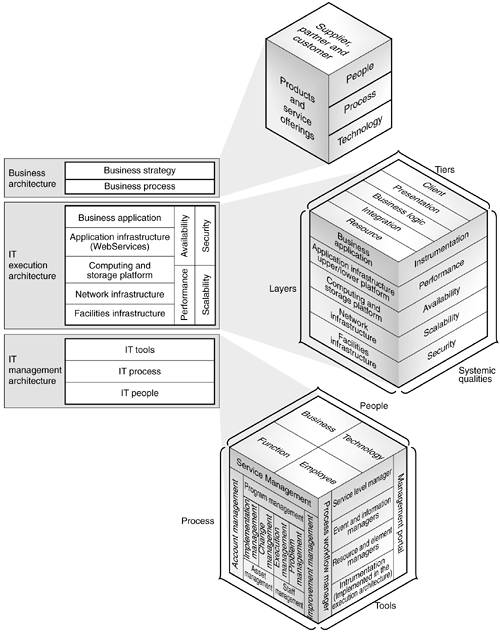
| In Chapter 3, we introduced an abbreviated version of the E-stack. The E-stack construct shown in the following figure is extended to illustrate all the components and interactions that must be addressed when an organization delivers IT-based services to internal or external customers. The architecture process is a complex, high-level set of tasks that considers the inputs, outputs, and dependencies of an IT service on the existing IT environment, along with the definition and mapping of requirements to technology. Sun Professional Services (SunPS SM ) developed the E-stack to help organize these considerations and to ensure that they are addressed during the course of solutions architecture development. The need to address the components of the E-stack drives three separate but related architectural disciplines. The following figure illustrates this mapping and is followed by a brief overview of the business and execution architectures. Details about the management architecture are provided in later sections. Figure 8-1. Structure of the E-Stack Business ArchitectureThe business architecture captures the activities and requirements that drive the IT architecture process and IT management environment. It consists of the various products and services that are core to the organization's business, the relationships with the organization's key external stakeholders (suppliers, partners , customers), and the people, processes, and technologies required to support the production and distribution of the organization's products and services. Execution ArchitectureThe execution architecture hosts the pieces of business applications and their supporting infrastructure (for example, hardware, software, and networks). The layers of the execution architecture describe the various technology components that make up a business application, system, and the supporting environment. They include the following:
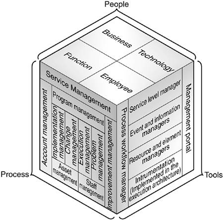
The tiers of the execution architecture describe the logical partitioning of functions within a distributed application. References to n- tier applications are, in effect, describing this face of the execution architecture. Systemic qualities serve to capture the various non functionality requirements that must be considered during the architectural process. These considerations will not impact how an application will work, but rather how well it will work. Their position as the third face of the IT execution architecture means that these requirements are considerations at each intersection of the tiers and layers faces. The use of layers and tiers serves to communicate and enforce common best practices of architecture development, such as separation of concerns and the use of well-defined interfaces. The result is a construct that allows the architect to decompose an application and evaluate its components at the intersection of the three faces. Special attention should be paid to the instrumentation component of the execution architecture (systemic quality). Instrumentation is the interface between the management architecture and execution architectures. The degree to which this quality is considered and implemented will determine how much visibility into the execution architecture is provided to external entities represented by the management architecture tools face. SunTone Management ArchitectureThe following figure illustrates the SunTone Management Architecture, sometimes referred to as the management cube . As seen below, the SunTone Management Architecture consists of three different axes or faces, each detailing a portion of an organization's IT management infrastructure. The following sections describe this construct in detail. Figure 8-2. SunTone Management Architecture PeopleThe people face of the SunTone Management Architecture represents the human aspects of the IT management environment. It describes all best practices in this area. These practices are based on the people capability maturity model (P-CMM) developed by the Carnegie Mellon Software Engineering Institute, and include the following main categories:
ProcessThis section describes the IT management processes, as defined in the SunTone Management Architecture. These processes are autonomous, to an extent, so they can be implemented independently. The main requirement to link any related process to another process is that you provide the appropriate input and create the appropriate output for the next process. FIGURE 8-3 on page 138 illustrates this interaction. Figure 8-3. IT Management Master Process The three major management components in the SunTone Management Architecture include the following:
ToolsThe tools portion of the SunTone Management Framework (STMF) is a functional taxonomy of the technology that facilitates control of the IT environment. This tools solutions model is described in a product-neutral fashion and should not be confused with technology-specific frameworks offered by various software vendors . The intent of this model is to quantify the scope of the technology solution, define the high-level components required, specify the necessary integration of components, and assist in mapping available technology to specific functional areas. Realization of a complete technology infrastructure for management of the IT environment requires use of the solutions model as the basis of an architecture effort that defines the requirements and associated solutions at a level of detail sufficient for implementation. The following figure shows the STMF tools solutions model. Figure 8-4. STMF Tools Solution Model As shown in the preceding figure, the solutions model is a layered set of functional components. As we move up the model, the focus of the components shifts from low-level interactions with the managed environment, to the management of information about the environment, to a focus on the services that support the organization's business. The process workflow and portal components enable the integration of the different components, the automation of IT business processes, and the presentation of management information, as shown in the following figure. Note that the various components of the tools solutions model are categorized by function as opposed to process. A common error is to attempt to categorize management technology along the process face of the framework ”for example, attempting to obtain a "problem management" tool or "performance management" package. This quickly becomes confusing because certain tools can support multiple processes, and each process will rely on the application of more than one tool. The following sections briefly describe each layer and component of the tools solutions model. InstrumentationThe instrumentation layer consists of all management elements that allow the various management tools to gain access to managed resources. Instrumentation is generally implemented within the context of the environment in which managed resources reside. Note that the entire managed stack is a candidate for instrumentation. The focus should not just be on the hardware and operating systems layers, but should also address the following items:
Instrumentation components may or may not be provided as part of a management component in another layer. Certain management tools include agent technology as part of the product. By contrast, hardware and software vendors might provide with their product an agent with their product that can communicate with other vendors' management tools through a defined protocol such as SNMP. Element and Resource Management LayerThis layer of the model consists of management applications, like those listed below, that directly interact with the managed environment to query or modify managed resources. Management applications perform one or more of the following functions shown in FIGURE 8-5 on page 141:
Figure 8-5. Tasks Enabled by Process Workflow and Portal Components Event and Information ManagersThis layer of the model consists of applications that manage events and information generated by the lower layers of the model. The focus of the applications at this layer shifts from dealing with the measurement and modifications of technical metrics to the management of data and alarms. The functional components at this layer are as follows :
Service Level ManagersService level managers (SLMs) are applications that provide the tie-in between business requirements as defined by SLAs and the technical status of the execution environment as determined by the lower layers of the framework. The functional components of service level managers include the following:
Process Workflow ManagersWe use workflow technology to automate the management processes described on the process face of the management framework cube. Examples of this type of technology include a trouble ticket system that supports the problem management process, or the automation of a change approval system that supports the change management process. Although we maintain a loose coupling between the process and tools portions of the framework, it is important to realize that process is one of the methods used to integrate the various components of the management architecture. Management PortalThe management portal is a collection of applications that enable external entities to access selected portions of the management framework. Examples of this type of application include a web interface for reviewing SLM reports , web or other types of user interfaces for the various tools, and an application used by end users to submit requests for service. It should also be possible, and it is even desirable, to use this portal to expose management information and facilities to people outside the IT organization. A fully realized portal implementation would provide standard portal functionality to include application and content aggregation, and personalization. Operational Capability and MaturityGiven the three architectures and the complexity associated with them, there is a tendency to address issues or provide capabilities with the wrong architecture. Systems analysts used to have an axiom that said when you automate a poorly designed business process, you wind up with a poorly designed system. That would be one example of attempting to solve a business architecture issue using the IT execution architecture. Problems must be solved and solutions must be provided within the correct architecture. Attempts to solve business process issues by applying just technology (execution architecture), or attempts to address architectural shortcomings of an application by using IT management architecture components are, at best, inefficient, and in many cases will not work. Operational CapabilityIn addition, it is important to realize what an existing IT environment's management capabilities are. Operational capability is considered to be the ability to deliver IT services to an agreed-on service level in a predictable fashion with acceptable risk and cost. The level of implementation of the SunTone management architecture creates the level of operational capability. The following figure shows the interaction of the faces and the formal definition of operational capability. Figure 8-6. Interactions of Operational Capability MaturityOur definition of organizational maturity is based on industry experience and the notion that capabilities increase over time as IT organizations mature. Identifying the level of maturity that applies to your environment enables you to make decisions about how to best manage the environment and how to plan for its evolution. There are many models for categorizing the maturity of the organization, including those provided by Carnegie Mellon, Gartner Group, and IDC. |

| < Day Day Up > |
EAN: 2147483647
Pages: 70
- Using SQL Data Definition Language (DDL) to Create Data Tables and Other Database Objects
- Using Data Control Language (DCL) to Setup Database Security
- Performing Multiple-table Queries and Creating SQL Data Views
- Working with Comparison Predicates and Grouped Queries
- Monitoring and Enhancing MS-SQL Server Performance