Chapter 2 - Internet Protocol (IP) Addresses

Chapter 2: Internet Protocol (IP) Addresses  
  Overview  
  A complete understanding of unicast and multicast IP addressing is required in order to design and implement robust IP networks. Concepts such as subnetting and Variable Length Subnet Masks (VLSM) should be mastered so that IP addressing plans make efficient use of your assigned address space. The concept, operation, and configuration of IP unicast routing protocols, RIP, IGRP, EIGRP, and OSPF, also need to be mastered because most multicast routing protocols rely on the underlying unicast routing configuration.
IP Address Format  
  An IP address is a 32-bit number that can be represented in many formats. Routers and computers are designed to operate efficiently on binary numbers, so a binary representation is a natural way for them to store and manipulate IP addresses. A typical 32-bit IP address to a router would look something like this:  
  10011100000110100001111000111100  
  This may be a fine representation for routers, but for us it is not the most appealing method. So let s take a look at the binary representation and see if we can find a way to represent these numbers using a method that may be a bit more palatable. One way is to simply represent the IP address as a decimal number. The binary number used in the example above has a decimal value of  
  2,618,957,372  
  This may be easier to read, but the size of the number makes it cumbersome to work with. Another representation scheme is to break up the binary number into pieces and represent each piece as a decimal number. A natural size for binary pieces is 8 bits, which is the familiar byte or not-as-familiar octet (octet is the telecommunication term, but the two words can be used interchangeably). So let s take our binary number, write it using groups of 8 bits (four octets) and then represent each group as a decimal number.  
  10011100  
  00011010  
 
  00011110  
 
  00111100  
 
  156  
  26  
 
  30  
 
  60  
 
  Table 2-1: Range of IP Addresses  


Low  
 
High  


  Binary  
0000000000000000000
0000000000000
 
 
11111111111111111111111111111111  
 
  Decimal  
0  
 
4,294,967,295  
 
  Dotted Decimal  
0.0.0.0  
 
255.255.255.255  


  We don t need all that space between the numbers, so let s use a period, or dot, as a separator. Now our IP address has the form  
  156.26.30.60  
  which is referred to as dotted decimal notation. How many IP addresses are there? The range of IP addresses in all our representation schemes is shown in Table 2-1.  
  Theoretically, there are 4,294,967,296 possible IP addresses, although we will discover in this chapter that the actual usable number of IP addresses is much smaller.  
  Classful IP Addressing  
  For a protocol to be routable, its address structure must be hierarchical, meaning that the address must contain at least two parts. For IP addresses, these parts are the network portion and the host portion. A host is an end station such as a computer workstation, router interface, or printer, while a network consists of one or more hosts. Figure 2-1 is a simple network consisting of two networks connected by a two-port router. The address of each host on this network, including the router interfaces, is given by its network and host numbers.  
   
  Figure 2-1: Hierarchical addressing  
  When the IP address scheme was designed, the decision was made to create five classes of IP addresses simply named Class A, B, C, D, and E. The logic behind the first three network classes was that the IP addressing scheme would be used for a few networks with a large number of hosts (Class A), a moderate number of networks with a moderate number of hosts (Class B), and a large number of networks with a small number of hosts (Class C). Class D addresses would be used for multicasting and Class E addresses would be reserved for experimental use.  
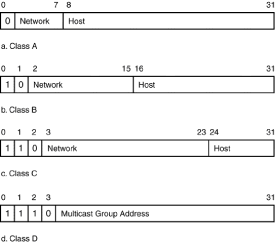
  Having three classes of IP addresses to handle different size networks requires that the network part and the host part for each address class have unequal sizes. The breakdown for the allocation of bits for the network and host portion for the first four IP address classes is shown in Figure 2-2.  
   
  Figure 2-2: Classful IP address structure  
  Class A addresses use 8 bits to identify the network and 24 bits to identify the host with the most significant bit of the first octet set to zero. Class B addresses use 16 bits to identify the network and 16 bits to identify the host with the first two bits of the first octet set to 1 0. Class C addresses use 24 bits to identify the network and 8 bits to identify the host with the first 3 bits of the first octet set to 1 1 0.  
  Class D or multicast addresses differ from unicast addresses in their interpretation.  
  A Class A, B, or C address is used to identify a network and a host on that network. A Class D multicast address is used to identify a group of receivers and senders of multicast traffic. Additionally, multicast senders and receivers can be present on any network.  
  If we examine the first octet of each class, we can see that the range of values for the four classes is  
  00000001 (1) 01111110 (126) for Class A  
  10000000 (128) 10111111 (191) for Class B  
  11000000 (192) 11011111 (223) for Class C  
  11100000 (224) 11101111 (239) for Class D  
  Looking at the first octet of the IP address can easily identify the network class. For example, the address used previously, 156.26.30.60, is a Class B address because the first octet is between 128 and 191. Another (and more tedious) way to identify the class is to represent the first octet of the address in binary and see what the first couple of bits are set to. For example, 156 equals 10011100 in binary. The first two bits are 1 0, so according to Figure 2-1, this is a Class B address.  
  How many Class A, B, and C networks are there? Class A networks use 7 bits for the network ID, so 128 Class A networks are possible. Class B addresses use 6 bits from the first octet and all 8 bits of the second octet, so there are 16,384 networks (64 x 256), 64 from the first octet and 256 from the second octet. Class C addresses use 5 bits from the first octet, 8 bits from the second octet, and 8 bits from the third octet, so there are 2,097,152 possible Class C networks (32 x 256 x 256). Class D addresses are not associated with networks but with multicast groups.  
  Class A, B, and C addresses are unicast addresses. Each IP address in the first three classes is used to identify a particular and unique Internet host, while a Class D address is used to identify a group of hosts belonging to a particular IP multicast group. The multicast addresses are in the range 224.0.0.0 through 239.255.255.255 (currently assigned multicast addresses are listed in Appendix B). The range of addresses between 224.0.0.0 and 224.0.0.255, inclusive, is reserved for the use of routing protocols and other low-level topology discovery or maintenance protocols, such as gateway discovery and group membership reporting. Multicast routers should not for ward any multicast datagram with destination addresses in this range, regardless of the TTL.  
  How many hosts can each network have? Class A networks have 24 bits to identify a host; this equals 1,677,216 possible hosts per network! Class B networks have 16 bits to identify a host, which equals 65,536 hosts, and Class C networks have 8 bits to identify a host, which equals 256 possible hosts. Table 2-2 lists the capabilities for Class A, B, and C addresses.  
  Table 2-2: IP Classful Address Capabilities  
 
 
  Class  
Networks  
 
Hosts  


  A  
0,000,126  
 
16,777,214  
 
  B  
0,016,384  
 
00,065,534  
 
  C  
2,097,152  
 
00,000,254  


  You may have noticed that the number of hosts listed in Table 2-1 is always two less than the number calculated. The reason for this discrepancy is that two special addresses can t be assigned to a host. A host address of all ones is the broadcast address for a particular network, and a host address of all zeros is used by a host to temporarily identify itself ( this host ) until it has been assigned an IP address. Only 126 Class A networks exist because network 0 cannot be used, and network 127 is reserved for the loopback address that is used for testing interprocess communication. When a host sends a packet to 127.0.0.1, the data is not sent on the network but is returned immediately to the sending host.  
  The IP address blocks listed below have been reserved for private Internets.  
  11110.0.0.0 10.255.255.2550  
  1172.16.0.0 172.31.255.2550  
  192.168.0.0 192.168.255.255  
  These private IP addresses should never be advertised on the Internet because they can be used by any private Internet. If these addresses are used, then a technique such as network address translation would need to be used in the private Internet to be connected to the public Internet.  
  Classful IP address assignments can be extremely inefficient as the following design problem demonstrates. Assume we are designing a network for a campus that has approximately 1500 nodes or end-stations. Also assume that the predicted future growth of the network over the next five years will be no more than 5000 nodes. At first glance, it would seem that a Class B network would suffice for the current network requirements and also leave plenty of room for future growth. Having 1500-plus nodes (5000-plus in the future) would be a very large ethernet collision domain. If we want to limit the number of nodes on an ethernet segment to no more than 100, then we need 50 networks to accomplish our design. Regardless of which class of IP network addresses we decide to use (assuming we could choose any addresses we want), there will be an enormous waste of IP addresses as shown in Table 2-3.  
  Table 2-3: IP Address Design Inefficiencies  
 
 
  Network Class  
Addresses Required  
 
Addresses Available  
 
Addresses Wasted  


  A  
100  
 
16,777,214  
 
16,777,114  
 
  B  
100  
 
00,065,534  
 
00,065,434  
 
  C  
100  
 
00,000,254  
 
00,000,154  


  Now multiply each entry in Table 2-3 by the 50 networks that are required and you can easily see that regardless of which address class we choose, an enormous number of IP addresses will be wasted. Also, if we are to have connectivity to the Internet, then the network will have to advertise 50 networks to the Internet routers. Multiply that by the number of campuses in the world and you have a situation where the size of the Internet routing tables becomes unmanageable. How do we overcome these problems? In a word, subnetting.
IP Subnets  
  The solution to our design problem is to divide whatever class of IP address we are assigned into a number of smaller networks with fewer hosts per network. This is accomplished by borrowing bits from the host portion of our IP address and using them in the network portion. How do we and, more importantly, how does a router know how many bits to use for the network and how many to use for the host? The answer is by using a subnet mask.  
  A subnet mask is a 32-bit binary number that identifies which bits in the address are used for the host and which bits are used for the network. A one in the mask identifies the corresponding bit in the IP address as a network bit, and a zero in the mask identifies the corresponding bit in the IP address as a host bit. A router accomplishes this operation by performing a bitwise AND operation with the IP address and the subnet mask.  
  0 AND 1 5 0  
  1 AND 0 5 01 AND 1 5 1  
  As an example, consider the IP address/subnet mask pair  
  156.26.30.60/255.255.240.0  
  which has the binary representations  
  Address  
  10111100  
 
  00011010  
 
  00011110  
 
  00111100  
 
  Mask  
  11111111  
 
  11111111  
 
  11110000  
 
  00000000  
 
  Performing the AND operation yields  
  000110100001000000000000  
  Converting the result to dotted decimal notation yields the network portion of the IP address  
  156.26.16.0  
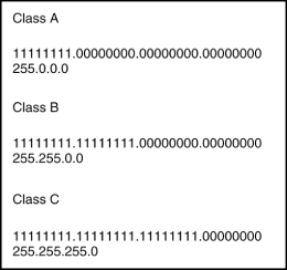
  One subnet mask restriction is that the 1 bits in the mask must be contiguous. Because of this, an alternative representation for the mask is just to indicate how many 1 bits are in the mask. For example, the IP address/ subnet mask pair in the previous example can be written as 156.26.30.60/20. The subnet masks for non-subnetted networks are shown in Figure 2-3.  
   
  Figure 2-3: Standard IP subnet masks  
  Subnet masks never have fewer ones than the masks listed in Figure 2-3. A Class C address, for example, cannot have a subnet mask of 255.255.0.0. Request for Comment (RFC) 950 first defined the subnetting of IP addresses and does not allow the use of the all-zeros and all-ones subnet, so we will initially look at subnetting examples that obey these restrictions. In later examples, we will see how we can remove these restrictions with the use of an appropriate routing protocol, such as OSPF. The number of subnet bits cannot be one because of the restriction in RFC 950 (see Tables 2-4, 2-5, and 2-6). A 1-bit subnet mask would have a value of either zero (all zeros) or one (all ones) and this is not allowed.  
  Table 2-4: Class A Subnet Masks  
 
 
  Number of Subnet bits  
Subnet Mask  
 
Number of Subnetworks  
 
Number of Hosts/Subnet  
 
Total Number of Hosts  


  1  


  2  
255.192.0.0  
 
0000002  
 
4194302  
 
08388604  
 
  3  
255.224.0.0  
 
0000006  
 
2097150  
 
12582900  
 
  4  
255.240.0.0  
 
0000014  
 
1048574  
 
14680036  
 
  5  
255.248.0.0  
 
0000030  
 
0524286  
 
15728580  
 
  6  
255.252.0.0  
 
0000062  
 
0262142  
 
16252804  
 
  7  
255.254.0.0  
 
0000126  
 
0131070  
 
16514820  
 
  8  
255.255.0.0  
 
0000254  
 
0065534  
 
16645636  
 
  9  
255.255.128.0  
 
0000510  
 
0032766  
 
16710660  
 
  10  
255.255.192.0  
 
0001022  
 
0016382  
 
16742404  
 
  11  
255.255.224.0  
 
0002046  
 
0008190  
 
16756740  
 
  12  
255.255.240.0  
 
0004094  
 
0004094  
 
16760836  
 
  13  
255.255.248.0  
 
0008190  
 
0002046  
 
16756740  
 
  14  
255.255.252.0  
 
0016382  
 
0001022  
 
16742404  
 
  15  
255.255.254.0  
 
0032766  
 
0000510  
 
16710660  
 
  16  
255.255.255.0  
 
0065534  
 
0000254  
 
16645636  
 
  17  
255.255.255.128  
 
0131070  
 
0000126  
 
16514820  
 
  18  
255.255.255.192  
 
0262142  
 
0000062  
 
16252804  
 
  19  
255.255.255.224  
 
0524286  
 
0000030  
 
15728580  
 
  20  
255.255.255.240  
 
1048574  
 
0000014  
 
14680036  
 
  21  
255.255.255.248  
 
2097150  
 
0000006  
 
12582900  
 
  22  
255.255.255.252  
 
4194302  
 
0000002  
 
08388604  
 
  23  


  24  


  Table 2-5: Class B Subnet Masks  
 
 
  Number of Subnet Bits  
Subnet Mask  
 
Number of Subnetworks  
 
Number of Hosts/Subnet  
 
Total Number of Hosts  


  1  


  2  
00255.255.192.0  
 
00002  
 
16382  
 
32764  
 
  3  
00255.255.224.0  
 
00006  
 
08190  
 
49140  
 
  4  
00255.255.240.0  
 
00014  
 
04094  
 
57316  
 
  5  
00255.255.248.0  
 
00030  
 
02046  
 
61380  
 
  6  
00255.255.252.0  
 
00062  
 
01022  
 
63364  
 
  7  
00255.255.254.0  
 
00126  
 
00510  
 
64260  
 
  8  
00255.255.255.0  
 
00254  
 
00254  
 
64516  
 
  9  
255.255.255.128  
 
00510  
 
00126  
 
64260  
 
  10  
255.255.255.192  
 
01022  
 
00062  
 
63364  
 
  11  
255.255.255.224  
 
02046  
 
00030  
 
61380  
 
  12  
255.255.255.240  
 
04094  
 
00014  
 
57316  
 
  13  
255.255.255.248  
 
08190  
 
00006  
 
49140  
 
  14  
255.255.255.252  
 
16382  
 
00002  
 
32764  
 
  15  


  16  


  Table 2-6: Class C Subnet Masks  
 
 
  Number of Subnet Bits  
Subnet Mask  
 
Number of Subnetworks  
 
Number of Hosts/Subnet  
 
Total Number of Hosts  


  1  


  2  
255.255.255.192  
 
02  
 
62  
 
124  
 
  3  
255.255.255.224  
 
06  
 
30  
 
180  
 
  4  
255.255.255.240  
 
14  
 
14  
 
196  
 
  5  
255.255.255.248  
 
30  
 
06  
 
170  
 
  6  
255.255.255.252  
 
62  
 
02  
 
124  
 
  7  


  8  


  A 15-bit subnet mask for Class B and a 7-bit subnet mask for Class C is also illegal because it would leave only 1-bit for the host, which we have seen cannot be all zeros or all ones. A 16-bit subnet mask for Class B or an 8-bit subnet mask for Class C makes no sense because this would leave zero host bits.  
  Subnet Examples  
  In the following examples, determine if the address/subnet pair is legal. If it is legal, determine the network number and the range of host addresses for that network. Also determine for the mask, the number of available networks and available hosts per network.  
  1.   IP address = 193.144.233.130  
    Subnet mask 5 255.255.255.192  
      For a Class C address, we only need to look at the last octet of the address and the mask.  
    130 = 1000 0010  
    192 = 1100 0000  
      This is a legal pair because neither the subnet nor the host is all zeros or all ones.  
  Network equals 193.144.233.128 because the mask selects the upper two bits of the address (130) and the rest of the bits are set to zero to identify the network.  
  Range of hosts = 193.144.233.129 193.144.233.190.  
  The host portion (last six bits) can have values ranging from 000001 to 111110 (remember they can t be all zeros or all ones). Add in the subnet portion, which is the upper two bits of the address (in this case, 1 0), and you have 10 000001 to 10 111110 for the host addresses.  
    From Table 2-6, the number of available networks is 2 and the number of hosts is 62.  
  2.   IP address = 156.26.30.60  
    Subnet Mask = 255.255.255.0  
  This is relatively easy because the entire third octet is used for the subnet and the entire fourth octet is used for the host. This is a legal pair because neither the subnet nor the host is all zeros or all ones.  
    Network = 156.26.30.0  
    Range of hosts = 156.26.30.1 156.26.30.254  
    From Table 2-5, the number of networks is 254 and the number of hosts is 254.  
  3.   IP address = 199.200.201.50  
    Mask = 255.255.255.128  
  This is illegal because the subnet mask only borrows 1 bit from the host and that bit has to be either zero or one.  
  4.   IP address = 191.200.201.50  
    Mask = 255.255.255.128  
      This is a legal pair because the address is Class B and we are borrowing 9 bits from the host portion.  
    Network = 191.200.201.0  
    Range of hosts = 191.200.201.1 191.200.201.126  
      From Table 2-5, the number of networks is 510 and the number of hosts is 126.  
  Subnetting can be viewed as creating a three-part hierarchical address. The network portion of the address can be found by applying the standard subnet mask to the IP address (refer to Figure 2-3). The subnet is determined from the bits borrowed from the host portion and the host number is simply those bits that are left over. For an example, we will examine the Class B address/mask pair  
  144.223.0.0/255.255.255.0  
  and determine the network number, the subnetwork numbers, and the range of host numbers. The network number is found by applying the standard Class B 16-bit subnet mask, which yields the network  
  144.223.0.0  
The subnet is the entire third octet, so the 254 subnets are
  144.223.1.0  
  144.223.2.0  
  .  
  .  
  .  
  144.223.254.0  
  and the range of hosts for each subnet is 1 to 254. Now let s try a bit more complicated example. Consider the address/mask pair  
  144.223.0.0/255.255.255.224  
  The network number is still 144.223.0.0. The subnet mask borrows 11 bits from the host portion of the address. The first 8 bits borrowed include the entire third octet, which has a value of 0 to 255. The 3 bits borrowed from the third octet have the values  
  00000000=0  
  00100000=32  
  01000000=64  
  01100000=96  
  10000000=128  
  10100000=160  
  11000000=192  
  11100000=224  
  Why are the values 0 (all zeros) and 255 (all ones) for the third octet, and 0 (all zeros) and 224 (all ones) from the fourth octet included? The third octet can be 0 if the 3 bits in the fourth octet are not zero. The third octet can also be all ones if the 3 bits in the fourth octet are not all ones. The 3 bits in the fourth octet can be all zeros if the third octet is not all zeros, and the 3 bits from the fourth octet can be all ones if the third octet is not all ones. In other words, the 11 subnet bits cannot be all zeros or all ones. Therefore, the range of subnet numbers is  
  144.223.0.32  
  144.223.0.64  
  .  
  .  
  .  
  144.223.0.224  
  144.223.1.0  
  144.223.1.32  
  .  
  .  
  .  
  144.223.255.0  
  .  
  .  
  .  
  144.223.255.192  
  Determining the range of host addresses for each subnet requires more effort. The bit pattern for the fourth octet of network 144.223.0.32 is  
  001 hhhhh  
  where hhhhh represents the host number, which cannot be all zeros or all ones. Therefore, the first legal host number is 00001, making the fourth octet  
  00100001 = 33  
  so the first host address is  
  144.223.0.33  
  and the last legal host bit pattern for the fourth octet is  
  00111110 = 62  
  which gives the range of hosts addresses for the first subnet as  
  144.223.0.33 144.223.0.62  
  The broadcast address for each subnet is found by setting all the bits in the host portion to 1. The broadcast address for subnet 144.223.0.32 is determined by setting the last 5 bits of the fourth octet to 1 yielding  
  00111111 = 63  
  Putting it all together gives us the broadcast address  
  144.223.0.63  
  5.   Determine all the subnet numbers for the address/mask pair 193.128.55.0/255.255.255.240. Also determine the range of host addresses and the broadcast address for the fourth subnet.  
  Network  
Hosts  
 
  193.128.55.0  
1 14 (If IP subnet-zero is used)  
 
  193.128.55.16  
17 30  
 
  193.128.55.32  
33 46  
 
  193.128.55.48  
49 62, Broadcast address = 193.128.55.63  
 
  193.128.55.64  
65 78  
 
  193.128.55.80  
81 94  
 
  193.128.55.96  
97 110  
 
  193.128.55.112  
113 126  
 
  193.128.55.128  
129 142  
 
  193.128.55.144  
145 158  
 
  193.128.55.160  
161 174  
 
  193.128.55.176  
177 190  
 
  193.128.55.192  
193 206  
 
  193.128.55.208  
209 222  
 
  193.128.55.224  
225 238  
 
  193.128.55.240  
241 254  
 
  IP Address Design Example 1  
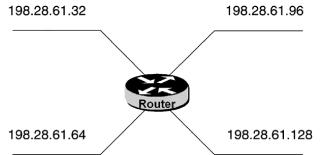
  Assume your company has been assigned the Class C address 198.28.61.0 and you have determined that you require four networks with a maximum of 25 hosts per network. From Table 2-6, you will need three subnet bits, resulting in a subnet mask of 255.255.255.224. The subnet numbers for this design are any four of the following, as shown in Figure 2-4.  
   
  Figure 2-4: IP address design example 1  
  198.28.61.32  
  198.28.61.64  
  198.28.61.96  
  198.28.61.128  
  198.28.61.160  
  198.28.61.192  
  Although subnets solve some of the problems associated with the inefficient use of IP address space, situations occur when simple subnetting does not suffice. Consider the network in Figure 2-5 in which two routers are connected by a serial link. This serial link is a point-to-point connection, so there are only two hosts on the link, the two router interfaces. Each network must also be on a separate subnet, so no matter which subnet mask we choose, we will be wasting IP addresses. If we are using a Class B address with a 24-bit subnet mask, then the subnet assigned to the serial link will only use two out of a possible 254 host addresses.  
   
  Figure 2-5: Limitations of simple subnetting  
  If we could use different subnet masks for different subnetworks, then the limitations of Figure 2-5 could be solved. A subnet mask of 255.255.255.252 (or /30) can accommodate only two hosts, which is perfect for a point-to-point serial link. Unfortunately, this mask, if used throughout the network, would limit all subnets to two hosts. The ideal solution would be to vary the length of the subnet mask and adjust it according to the needs of each individual network.  
  Variable Length Subnet Masks  
  RFC 1009, 1987, specifies the procedures for using multiple subnet masks. This technique is referred to as variable length subnet masks (VLSM). The term VLSM can be confusing because the subnet mask for a specific network does not vary but is fixed. VLSM means that the subnet masks for different subnets can have unequal lengths. As an example, it would allow a subnet mask of 255.255.255.252 to be assigned to a serial link and 255.255.255.0 to an ethernet network. Once the masks are assigned, however, they do not change, at least by themselves.  
   
  Figure 2-6: VLSM example 1  
  The VLSM technique is very useful for allocating IP addresses more efficiently (less waste) and for reducing the size of routing tables. However, VLSM can also cause a number of massive network headaches if not used properly.  
  VLSM Example 1  
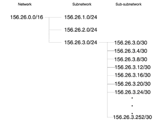
  Let s apply VLSM to the network in Figure 2-5. Assume we have been assigned the Class B network 156.26.0.0. The ethernet networks are assigned addresses using a /24 subnet mask; we will use the first two networks with this mask, 156.26.1.0 and 156.26.2.0. The third network, 156.26.3.0, will be sub-subnetted using a /30 subnet mask, which will give us a possible 62 sub-subnets we can use for serial connections. Notice that we are subnetting an already subnetted network, 156.26.3.0. Figure 2-6 illustrates this technique.  
  Figure 2-6 visually represents the technique that should be used when using VLSM. Start with the standard subnet mask (/8, /16, or /24 for Class A, B, or C). Determine the network with the required maximum number of hosts, in this case 254. Then subnet using a mask that will give you networks that can handle the largest number of hosts you need. For smaller networks, sub-subnet the large networks and keep going until you have satisfied your requirements.  
  VLSM Example 2  
  The best way to master a technique is practice, practice, practice, so here we go. Given the IP network 202.128.236.0, design a network with the following requirements:  
    Four networks with a maximum of 26 hosts  
    Three networks with a maximum of 10 hosts  
    Four point-to-point serial links  
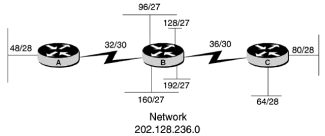
  Starting with the greatest number of hosts per network, we can use a /27 subnet mask to satisfy the first requirement. From Table 2-6, this gives us six networks of 30 hosts each with two networks left over to sub-subnet. To satisfy the next requirement, we can sub-subnet the two leftover /27 networks using a /28 subnet mask to give us four networks with 14 hosts each. Finally, take one of the four sub-subnetted networks and sub-sub-subnet using a /30 subnet mask.  
  How did I arrive at the diagram in Figure 2-7? Let s take a closer look as to where these network numbers came from; then we ll look at another VLSM design problem to ensure that you have mastered the technique.  
   
  Figure 2-7: VLSM example 2  
  1.   Determine the mask for the networks containing the greatest number of hosts.  
  The first requirement is for four networks with a maximum of 26 hosts. Using Table 2-6, we need three subnet bits or a /27 subnet mask. The fourth octet of our IP network would be segmented as  
  S S S H H H H H  
  where S S S indicates the subnet bits and H H H H H indicates the host bits. The subnets then are  
  0 0 1 0 0 0 0 0=32  
  0 1 0 0 0 0 0 0=64  
  0 1 1 0 0 0 0 0=96  
  1 0 0 0 0 0 0 0=128  
  1 0 1 0 0 0 0 0=160  
  1 1 0 0 0 0 0 0=192  
  and we are using subnets 96 through 192 for the networks containing 26 hosts because these subnets can handle a maximum of 30 hosts.  
  2.   Sub-subnet the subnetted networks as needed.  
  The second requirement calls for three networks with a maximum of 10 hosts each. Again, we consult Table 2-6 and see that we need four subnet bits or a /28 subnet mask. We will sub-subnet network 202.128.236.32 and 202.128.236.64. The first three subnet bits are fixed with the values 001 (subnet 32) and 010 (subnet 64), so now we have  
  0 0 1 S H H H H  
  0 1 0 S H H H H  
  Network 32 S can be 0 or 1, giving us  
  0 0 1 0 H H H H  
  0 0 1 1 H H H H  
  Setting the host bits to 0, the sub-subnets are  
  0 0 1 0 0 0 0 0 = 32  
  0 0 1 1 0 0 0 0 = 48  
  Applying the same procedure to subnet 64, we get  
  0 1 0 0 0 0 0 0 = 64  
  0 1 0 1 0 0 0 0 = 80  
  3.   To satisfy the last requirement of four point-to-point serial links, we will sub-sub-subnet sub-subnet 32, which now is equal to  
  0 0 1 0 S S H H  
  S S can be either 0 0, 0 1, 1 0 , or 1 1 yielding  
  0 0 1 0 0 0 0 0 = 32  
  0 0 1 0 0 1 0 0 = 36  
  0 0 1 0 1 0 0 0 = 40  
  0 0 1 0 1 1 0 0 = 44  
  As a final task for this exercise, determine the range of hosts and the broadcast addresses for networks 202.128.236.192, 202.128.236.80, and 202.128.236.40.  
  The fourth octet of network 202.128.236.192 is  
  1 1 H H H H H H  
  and the host bits can range from  
  0 0 0 0 0 1 1 1 1 1 1 0  
  which gives us a range of  
  1 1 0 0 0 0 0 1 (193) 1 1 1 1 1 1 1 0 (254)  
  The broadcast address is determined by setting the host bits to 1, which is  
  1 1 1 1 1 1 1 1 5 255  
  so the broadcast address is 202.128.236.255. For network  
   
  Figure 2-8: Realization of VLSM example 2  
  202.128.236.80, the fourth octet contains  
  0 1 0 1 H H H H  
  so the range of host addresses is  
  0 1 0 1 0 0 0 1 (81) 0 1 0 1 1 1 1 0 (94)  
  and the broadcast address is  
  0 1 0 1 1 1 1 1 (95)  
  For network 202.128.236.40, the fourth octet contains  
  0 0 1 0 1 0 H H  
  Because H H cannot be 0 0 or 1 1, the host addresses for this network are 202.128.236.41 and 202.128.236.42 with a broadcast address of 202.128.236.243. The realization of this network design is shown in Figure 2-8.  
  For the final VLSM example, design a network using the Class C address 200.100.50.0 that satisfies the following requirements:  
    _Nine serial point-to-point links  
    _Four networks with a maximum of 30 hosts  
    _Three networks with a maximum of five hosts  
  Determine the address host ranges and the broadcast address for each subnet.  
  From Table 2-6, a 3-bit subnet mask will give us six networks of 30 hosts each.  
  Subnet mask = 255.255.255.224  
  Networks  
Hosts  
 
Broadcast Address  
 
  200.100.50.0  
1 30  
 
200.100.50.31 (if we use IP subnet-zero)  
 
  200.100.50.32  
33 62  
 
200.100.50.63  
 
  200.100.50.64  
65 94  
 
200.100.50.95  
 
  200.100.50.96  
97 126  
 
200.100.50.127  
 
  200.100.50.128  
129 158  
 
200.100.50.159  
 
  200.100.50.160  
161 190  
 
200.100.50.191  
 
  200.100.50.192  
193 222  
 
200.100.50.223  
 
  One solution is to use the first four networks to satisfy the requirement of four networks with 30 hosts each. For the requirement of three networks with five hosts each, we can sub-subnet network 200.100.50.160 using the 5-bit subnet mask 200.100.50.160/255.255.255.248, which gives us the networks listed below.  
  Network  
Hosts  
 
Broadcast Address  
 
  200.100.50.160  
161 166  
 
200.100.50.167  
 
  200.100.50.168  
169 174  
 
200.100.50.175  
 
  200.100.50.176  
177 182  
 
200.100.50.183  
 
  200.100.50.184  
185 190  
 
200.100.50.191  
 
  We can use any three of the four networks to satisfy the requirement of three networks with five hosts.  
  Finally we can sub-subnet the 200.100.50.192 network using a 30-bit subnet mask that gives us the networks listed below.  
  Network  
Hosts  
 
Broadcast Address  
 
  200.100.50.192  
193 194  
 
200.100.50.195  
 
  200.100.50.196  
197 198  
 
200.100.50.199  
 
  200.100.50.200  
201 202  
 
200.100.50.203  
 
  200.100.50.204  
205 206  
 
200.100.50.207  
 
  200.100.50.208  
209 210  
 
200.100.50.211  
 
  200.100.50.212  
213 214  
 
200.100.50.215  
 
  200.100.50.216  
217 218  
 
200.100.50.219  
 
  200.100.50.220  
221 222  
 
200.100.50.223  
 
  200.100.50.224  
225 226  
 
200.100.50.227  
 
  200.100.50.228  
229 230  
 
200.100.50.231  
 
  200.100.50.232  
233 234  
 
200.100.50.235  
 
  200.100.50.236  
237 238  
 
200.100.50.239  
 
  200.100.50.240  
241 242  
 
200.100.50.243  
 
  200.100.50.244  
245 246  
 
200.100.50.247  
 
  200.100.50.248  
249 250  
 
200.100.50.251  
 
  Choose any nine of the networks for the serial links.  
  Subnet masks can also be used with Class D multicast addresses. As an example, assume we have the following Class D address/mask pair.  
  225.250.250.0/255.255.255.0  
  This address mask/pair would then represent all the multicast groups from 225.250.250.0 225.250.250.255. The multicast address/mask pair can be used to summarize the range of groups that a router will allow or that a multicast entity will service. We will learn more about the use of a mask with a multicast address later in the book.  


Cisco Multicast Routing and Switching
Cisco Multicast Routing & Switching
ISBN: 0071346473
EAN: 2147483647
Year: 1999
Pages: 15

flylib.com © 2008-2017.
If you may any questions please contact us: flylib@qtcs.net