2.4 INTERNET MODEL
2.4 INTERNET MODEL
In this section, we introduce and briefly overview the Internet model that is used for TCP/IP networking. As illustrated in Figure 2.3, the Internet model consists of four layers, namely the network access layer, the Internet layer, the transport layer, and the application layer. This is somehow contradictory to the OSI-RM in which the Internet application layer is further divided into three distinct OSI layers (i.e., the application layer, the presentation layer, and the session layer), and the Internet network access layer is further divided into two OSI layers (i.e., the data link layer and the physical layer). The fact that the Internet model uses another layering structure than the OSI-RM should not be overemphasized and is mainly due to the fact that the Internet model was designed before the OSI-RM.
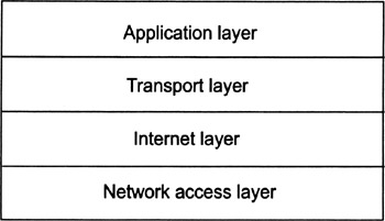
Figure 2.3: The Internet model and its four layers.
In the sections that follow, we overview and briefly discuss the four layers of the Internet model. Keep in mind that the explanations are fairly short and that you may refer to one of the references mentioned in the preface to get a more comprehensive picture about TCP/IP networking.
2.4.1 Network Access Layer
Part of the popularity of the TCP/IP communications protocol suite is due to its ability to be implemented on top of various local area network (LAN) technologies and corresponding network access layer protocols. Most of these protocols are specified by the Institute of Electrical and Electronic Engineers (IEEE) in its 802 series. Examples include IEEE 802.3 (mainly for Ethernet), IEEE 802.4 (mainly for Token Bus), and IEEE 802.5 (mainly for Token Ring). Following the terminology of the IEEE, these protocols are generally referred to as media access layer protocols. In addition, there are high-speed technologies and corresponding network access layer protocols, such as Fast Ethernet, Fiber Distributed Data Interface (FDDI), and Asynchronous Transfer Mode (ATM), as well as protocols to dial up and connect to TCP/IP networks, such as the Point-to-Point Protocol (PPP).
The predominant strategy today is to use Ethernet for local area networking, and to connect the Ethernet through a leased line (e.g., a T1 line) to an ISP that interconnects to the Internet. This is also the strategy that an organization new to TCP/IP networking is likely to use, if for no other reason than because many vendors of personal computers and workstations sell their systems with built-in Ethernet interfaces.
2.4.2 Internet Layer
In this section, we overview and briefly discuss the Internet Protocol (IP) and some of its routing and support protocols.
Internet Protocol
IP, as specified in RFC 791 [12] and STD 5, is by far the most important protocol in the entire TCP/IP communications protocol stack. In fact, the Internet layer is the only layer in the Internet model that is dominated by a single protocol (i.e., IP). Underneath and above the Internet layer, there are many protocols that coexist on each layer. The current version of IP is IP version 4, or IPv4. In this book, we use the term IP to refer to IPv4. If we refer to another version of IP, we usually append the corresponding version number.
In essence, IP provides a connectionless and unreliable datagram delivery service. What this basically means is that messages and application-specific data segments are split into datagrams (i.e., IP packets)[24] and that these IP packets are routed individually through the (inter)network. To allow each IP packet to be routed individually, it must include some source and destination address information in a unique address space. This address space allows us to construct large internetworks concatenated from many different physical networks. Each of these networks may use its own network access layer protocol and its own addressing scheme. IP provides a logical address space and a corresponding addressing scheme on top of them.
In practice, each host network interface must be configured with an IP address. As discussed later, this IP address must either be globally unique or private. If a host has more than one network interface, each interface must have a separate IP address. Network practitioners often refer to a host address when they really mean the host's network interface address. But keep in mind that hosts do not have IP addresses; network interfaces do. Unfortunately, the protocols specified in various RFC documents often use the term host address instead of network interface address, so, this nomenclature is followed in this book, although it is somehow misleading.
An IP (source or destination) address is 32 bits wide, resulting in a total address space of 232. The corresponding IP addresses are usually written in dotted-decimal notation, where each byte appears as a decimal number separated by periods, arranged from high-order byte to low-order byte. Primarily to simplify routing, an IP address is divided into two parts:
-
A network number;
-
A host number.
For all machines to communicate successfully, every network interface on the same physical network segment must have the same network number and a unique host number. Originally, IP used the high-order byte as the network number and the low-order 3 bytes as the host number. But soon after IP was specified, it became obvious that there would be more than 28 − 2 = 254 interconnected networks (the network numbers 0x00 and 0xFF are reserved). A specific encoding of the high-order bits in the high-order byte of the IP address lets the network number be 1, 2, or 3 bytes long, with the remaining byte(s) used for the host number. This encoding scheme divides the IP address space into five classes of IP addresses (i.e., class A through class E). Table 2.4 summarizes the five classes and their corresponding bit encodings. Class A through class C are the most commonly used classes of IP addresses today. Class D is reserved for multicast communications, and class E is still unused and reserved for future use except for one address. This address (i.e., the address 255.255.255.255) refers to "any host on this network." It can be used only as a destination address, and an IP packet with this destination address is broadcasted to the hosts on the same network segment as the sender of the IP packet.
| Class | Bit Encoding | Network Range | Host Range |
|---|---|---|---|
| | |||
| A | 0 | 0.0.0.0 to 127.0.0.0 | 0.0.0 to 255.255.255 |
| B | 10 | 128.0.0.0 to 191.255.0.0 | 0.0 to 255.255 |
| C | 110 | 192.0.0.0 to 223.255.255.0 | 0 to 255 |
| D | 1110 | 224.0.0.0 to 239.255.255.255 | — |
| E | 11110 | 240.0.0.0 to 255.255.255.255 | — |
When an IP address is written in dotted-decimal notation, it is fairly simple and straightforward to determine the class of the address from the bit encoding simply by referring to the value of the highest-order byte. Addresses in each class are numerically contiguous. IP allows the host number to be further subdivided by using subnets. More specifically, IP subnetting makes it possible to logically partition an IP address space, and to use each partition as if it belonged to a distinct IP network number. IP uses a network mask to determine which bits in the host number are to be used as a subnet number.
IP packetizes a message by creating an IP packet for each message or data segment it receives from transport layer. Each packet consists of an IP header, followed by a payload that may be used to encapsulate and hold a transport layer protocol data unit. As far as IP is concerned, the payload is just a sequence of arbitrary data bytes.
There are many books that cover IP networking in detail. For the purpose of this book, we are mainly interested in the IP header. As illustrated in Figure 2.4, an IP (i.e., IPv4) header consists of the following fields:
-
The 4-bit version field is used to indicate the number of the IP version. As mentioned earlier, the current version is 4, although the next version of IP (i.e., IP version 6) is already specified and being deployed.
-
The 4-bit header length field is used to indicate the length of the IP header. The minimum, and typical, size of an IP header is 20 bytes. Because the header length is always indicated in 32-bit words, the header length field is initialized with the number 5 in this case.
-
The 8-bit TOS field is used to indicate a type of service (TOS) or priority for the IP packet. Type of service processing is seldom used today, so this field is almost always set to the default value of zero.[25]
-
The 16-bit total length field is used to indicate the total length of the IP packet (including the header) in bytes.
-
The 16-bit identification, 3-bit flags, and 13-bit fragment offset fields are used to fragment and properly reassemble IP packets. Refer to any book on IP networking to learn about IP fragmentation and reassembly.
-
The 8-bit TTL field is used to indicate a time to live (TTL). The TTL value specifies the time in seconds that an IP packet may exist. The value is decremented by at least 1 each time the IP header is processed by a router or host. Unless the packet is queued in a buffer for a long period of time, the TTL value actually indicates the maximum number of intermediate routers a packet may cross before it is dropped. Whenever the TTL reaches 0, IP must drop the packet unconditionally. This feature prevents a packet from looping around an internetwork forever because of a routing error.
-
The 8-bit protocol field is used to indicate the protocol data that is encapsulated and carried in the payload of the IP packet. For example, the value 1 is used for ICMP, 6 for TCP, and 17 for UDP. Other values have been assigned to various protocols.[26]
-
The 16-bit header checksum field is used for error detection. It carries the 16-bit 1's complement sum of all 16-bit words in the IP header, and checks for transmission errors that may have occured accordingly. It is important to note that the header checksum covers the IP header only, and that the upper-layer protocols must handle error control for the encapsulated data themselves. For example, a packet can be lost on its route to the destination because of transmission errors or a router might deliberately drop a packet because of buffer space shortage. Also, IP may deliver a packet more than once. It is up to the protocols that compose the encapsulated payload to be aware of these problems and to take appropriate steps. IP simply moves packets through the internetwork using a best-effort algorithm.
-
The 32-bit source IP address field is used to carry the IP address of the host or network interface from which the packet originated.
-
The 32-bit destination IP address field is used to carry the IP address of the packet's final destination host or network interface, regardless of the number of intermediate routers the packet may pass through. Note that because each IP packet header contains a source and destination IP address, it is self-contained and may be routed independently to its destination.
-
The options field can be used to indicate the following options:
-
Source routing (enables an IP packet's route to be explicitly controlled);
-
Route recording (records the route of the packet);
-
Timestamping (adds a time stamp by each intermediate router);
-
Security (includes security options);
-
Padding (pads the IP packet header to an even 4-byte boundary).
From a security point of view, the IP source routing and security options are of primary interest. In short, IP source routing can be used to specify a direct route to a destination and return path back to the origin. The route could involve the use of other routers or hosts that normally would not be used to forward the packet to its destination. As source routing can be used to launch sophisticated attacks, it should be normally disabled on a security gateway. The IP security options are mainly used in environments that provide support for multilevel security, such as military applications [13]. IP security options can also be used to constrain routing decisions or to control cryptographic transformations.
-
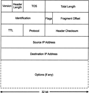
Figure 2.4: The format of an IP header (IPv4).
IP is not finished when it creates a packet. It also has to determine which network interface to use and then pass enough information to the network access layer protocol output module so it can properly encapsulate the IP packet in a corresponding frame. Frame formats are specific to each network access layer protocol. For example, when sending a packet on an Ethernet, IP passes to the output module the Ethernet destination address, the Ethernet-type field value that indicates that the encapsulated packet is an IP packet, and the IP packet itself. The Ethernet output module, in turn, sets the source Ethernet address to the Ethernet address of the network interface it uses to transmit the frame, calculates an Ethernet checksum, and generates a corresponding frame with header and trailer.
Because different transport protocols layered on top of IP can send messages that are larger than the frame size of the underlying network hardware, IP also does fragmentation of packets when they are transmitted on a network that cannot accomodate the original packet size or reassembly of the pieces of a previously fragmented packet.
The process of packetizing, framing, fragmenting, and reassembling are fundamental IP operations. They give IP the flexibility to operate with many different physical network media and transport layer protocols. As mentioned, IP fragmentation and reassembly are beyond the scope of this book and you may refer to any book on IP networking to learn about it.
IP next generation (IPng) is a name often used to refer to the next version of IP. This new version has been given the number 6.[27] IP version 6, or IPv6, builds on the architecture that made IPv4 successful, but is a complete redesign. The original claim was to address and substantially improve addressing and routing and to deal with long-term growth issues such as security, autoconfiguration, real-time services, and transition. The development of IPv6 is briefly overviewed in [14] and fully described in [15, 16]. The current IPv6 specification [17] has been approved by the IESG as a Draft Standard.
The major change from IPv4 to IPv6 is the increase in IP address size from 32 to 128 bits. In addition, some IPv4 header fields have been dropped or made optional to reduce the common-case processing cost of packet handling and to limit the bandwidth cost of the IPv6 header accordingly. Figure 2.5 illustrates the format of a basic IPv6 header. It consists of the following fields:
-
The 4-bit version field has remained unchanged from IPv4. It is still used to indicate the version number of IP. For IPv6 the value must be set to 6.
-
The 8-bit traffic class field is used to indicate the traffic requirements of the packet and is similar to the TOS field in the IPv4 header (in principle, it specifies a priority for the packet relative to other packets traveling across the network).
-
The 20-bit flow label field remains somehow experimental for IPv6. The flow label value, together with the source IP address, identifies a particular traffic flow in the network. Establishing flow labels is the responsibility of protocols other than IP such as, for example, the resource reservation protocol (RSVP).
-
The 16-bit payload length field is used to indicate the length of the IP packet payload data in bytes (i.e., the rest of the packet following the IPv6 header). Because this field is 16 bits in size, it normally limits IP packets to 65,535 bytes or less.
-
The 8-bit next header field identifies the type of header immediately following the basic IPv6 header. This field uses the same values as the IPv4 protocol field.
-
The 8-bit hop limit field is used to indicate a hop limit value. The value is decremented by 1 each node that forwards the IP packet. The packet is discarded if the value is decremented to zero. In short, the hop limit value determines how far a datagram will travel and is conceptually similar to the TTL field in IPv4.
-
The 128-bit source address field identifies the IP address of the originator of the IP packet.
-
The 128-bit destination address field identifies the IP address of the intended receiver of the IP packet.
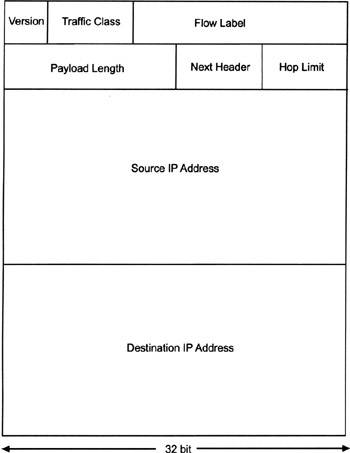
Figure 2.5: The IPv6 header format.
In IPv6, optional Internet layer information may be encoded in separate extension headers that are placed between the IPv6 basic header and the upper-layer protocol header. There is a relatively small number of extension headers, each identified by a distinct next header value. There are extension headers defined for hop-by-hop options, routing, fragment, destination options, authentication, and encapsulating security payload. With the exception of the last two, we are not going to further address IPv6 extension headers in this book.
Routing Protocols
The purpose of a routing protocol is to enable routing decisions to be made at the Internet layer. As such, the routing protocol must manage and periodically update the routing tables that are stored at each router. An Internet router may be part of an autonomous system, which is basically a collection of routers that are under a single administration. These routers run the same routing protocol, usually called an interior gateway protocol (IGP). There are several IGPs in use today, but all routers within an autonomous system normally run the same one. To communicate with another autonomous system, however, a router usually uses an exterior gateway protocol (EGP). The EGP does not know details of routing within another domain. To make an analogy, an IGP is like a local telephone exchange, whereas an EGP is more like a long-distance operator.
Today, a wide variety of routing protocols are used on the Internet. These routing protocols generally fall into two categories: reachability and distance vector protocols. A reachability protocol tells whether a path exists to a distant network. A distance vector protocol calculates a distance metric to this network. The distance metric can be just the number of routers between the source and destination network, or it can include more information about each link, such as bandwidth and load. In general, IGPs are distance vector protocols and EGPs are reachability protocols.
Internet routing an increasingly important and complex field of study. In fact, there are many books that entirely address Internet routing and corresponding protocols [18].
Support Protocols
There are several support protocols for IP to handle specific tasks, such as routing redirects, error messages, and mappings between IP addresses and physical network access layer addresses. These protocols do not make routing decisions at the Internet layer, although they can be used by protocols that do make such decisions.
-
The Address Resolution Protocol (ARP) as specified in RFC 826 (and STD 37) [19] can be used to find the network access layer address for a given IP address.
-
Contrary to ARP, the Reverse Address Resolution Protocol (RARP) as specified in RFC 903 (and STD 38) [20] can be used to find the IP address for a given network access layer address.
-
The Internet Control Message Protocol (ICMP) as specified in RFC 792 [21] is a required protocol that must be implemented in conjunction with IP (it is part of STD 5). It is used to send and receive control information between hosts.
-
The Internet Group Management Protocol (IGMP) as specified in RFC 1112 [22] is a protocol that can be used in an IP multicast environment to control host group memberships (it also is part of STD 5).
Support protocols are essential for the overall security of a TCP/IP implementation. For example, ICMP redirect messages can be used to fake routes and hosts acting as routers into using false routes. These false routes would aid in directing traffic to an attacker's system instead of a legitimate trusted system.
2.4.3 Transport Layer
The transport layer protocols make use of the packet delivery service provided by IP to provide transport layer services to applications. In short, there are two transport layer protocols: TCP and UDP. TCP provides a connection-oriented and reliable transport layer service, whereas UDP provides a connectionless and unreliable transport layer service.
Transmission Control Protocol
TCP as specified in RFC 793 and STD 7 [23] provides a connection-oriented and reliable transport layer service (i.e., a virtual circuit) to the communicating peers. More specifically, the sending TCP module processes a byte stream from an application process and divides it into distinct TCP segments that are sent to the receiving module on the other side of the TCP connection. The receiving TCP module, in turn, collects the TCP segments, recreates the original byte stream and passes it on to the corresponding application process.
Figure 2.6 illustrates the format of a TCP header. The header is put in front of the TCP segment.
-
Along with the source and destination IP addresses found in a packet's IP header, the 16-bit source port number and the 16-bit destination port number uniquely identify the two application processes associated with the TCP/IP connection.
-
The 32-bit sequence number field is used to indicate the relative byte offset of the first byte in the current message. The sequence number starts at an arbitrary 32-bit number that is negotiated when a TCP/IP connection is established. The field is examined only when the SYN bit is set (see the following discussion of the flags).
-
The 32-bit acknowledgment number field is used to acknowledge received data. In particular, its value indicates the relative byte position of the last byte successfully acknowledged. The field is examined only when the ACK bit is set (again see the following discussion of the flags).
-
The 4-bit header length field is used to indicate the number of 32-bit words in the TCP header, or the offset to the beginning of the Data field from the beginning of the header, respectively.
-
The 6-bit reserved field is reserved for future use. It is always set to zero.
-
The 6-bit flags field is used to indicate 1-bit values for the flags summarized in Table 2.5.

Table 2.5: TCP Flags Flag
Description
URG
This flag is used to send out data without waiting for the receiver to process data already in the stream. When the flag is set, the urgent pointer field is valid.
ACK
When the flag is set, the acknowledgment number field is valid.
PSH
The flag tells the TCP module to deliver data for this message immediately.
RST
When the flag is set, the connection is reset because of unrecoverable errors.
SYN
When the flag is set, the sequence number field is valid.
FIN
This flag is used to terminate a connection.
-
The 16-bit window size field is used to indicate the number of data bytes that the sender of a message is willing to accept. TCP uses this field for flow control and buffer management, which is very important in an internetwork with links of varying speed.
-
The 16-bit TCP checksum field is used for error detection. It usually carries the 16-bit 1's complement sum of each 16 bits in the header and data part of the message.
-
The 16-bit urgent pointer field is used to indicate the byte position of data in the message that should be processed first.
-
The options field may be used to specify various TCP options. These options, however, are very seldom used today.
-
Finally, the data field contains the payload data of the TCP message up to a maximum of 65,535 bytes.
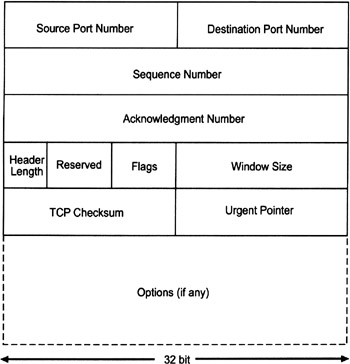
Figure 2.6: The TCP header format.
It should be noted at this point that the source and destination port numbers uniquely identify the application processes that send and receive messages. Port numbers are assigned to each client process running on a host; therefore, no two clients on the same host use the same port number for a TCP/IP connection. Client port assignments are enforced by the local host operating system. On the other side, well-known port numbers are assigned to server processes depending on the service they provide. For example, an SMTP server usually uses TCP port 25, a Telnet server TCP port 23, and an FTP server TCP port 21 for the control connection and TCP port 20 for the data connection. A server port number must be well known because it, along with the destination IP address, needs to be used when initiating a TCP/IP connection to a particular host and service. There is a general rule that only privileged server processes (i.e., those processes that operate with UNIX superuser privileges) can use port numbers less than 1,024. These port numbers are referred to as privileged ports. Servers mostly use privileged ports, whereas clients generally request unprivileged port numbers from the local operating system. Although this rule is not firm and is not required in the TCP/IP specifications, BSD-based UNIX systems generally adhere to it. Because client port assignments are unique for each host and servers use well-known ports, a unique address for each connection is the concatenation of the server IP address, the server port number, the client IP address, the client port number, and the transport layer protocol in use, such as TCP or UDP.
TCP uses a three-way handshake protocol to establish a connection, and to set the initial sequence numbers for each side of the connection accordingly. Referring to Figure 2.7, we assume the client on the left side wishes to establish a TCP connection to the server on the right side. Therefore, the client begins by sending a SYN message to the server. The SYN message is basically a TCP connection establishment request message with the SYN flag set and the client's initial sequence number X contained in the sequence number field. The server acknowledges the SYN message by sending a SYN-ACK message back to the client. The SYN-ACK message is a TCP message with both the SYN and ACK flags set, and containing the client's sequence number X in the acknowledgment number field and the server's sequence number Y in the sequence number field.[28] The client finishes establishing the TCP/IP connection by responding with an ACK message. This is a TCP message with the ACK flag set and the server's sequence number Y contained in the acknowledgment number field. From that moment on, the TCP/IP connection between the client and server is established and can be used for data transmission. None of the three messages contains any data; all information passed is conveyed in the TCP headers. Also note that the closing of the connection is handled by a two-way handshake protocol. When one side of the connection has finished sending data, it sends a message with the FIN flag set. Because the connection is full duplex, the other side can continue to send data until it also sends a message with the FIN flag set. In either case, a message with the RST flag set can be used to ultimately reset the connection.
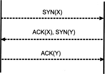
Figure 2.7: The TCP/IP three-way handshake connection establishment protocol
User Datagram Protocol
UDP as specified in RFC 768 and STD 6 [24] provides a connectionless and unreliable transport layer service to communicating peers. Because of the connectionless nature of UDP, there may be more than two peers involved in a UDP-based communication (e.g., multicast communications). Because UDP data units are delivered individually, they are also called datagrams. Each UDP datagram is encapsulated in an IP packet and UDP has the same notion of ports as TCP. Consequently, the destination port number and the source port number fields serve the same purposes as they do for TCP. Furthermore, a UDP message also includes a UDP length field that indicates the length of the message, as well as a checksum field that contains a checksum for the entire UDP header and message. Figure 2.8 illustrates the format of a UDP header.
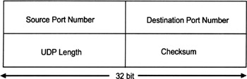
Figure 2.8: The UDP header format
UDP is a connectionless protocol, and as such it does not have a connection setup procedure. Because sequence numbers and window sizes need not be exchanged, neither the initial three-way handshake nor the closing two-way handshake are needed. A server process using UDP can simply receive datagrams from any client that sends the message to the server's port address. A UDP-based server's ability to receive UDP datagrams from any number of clients contrasts sharply with the TCP paradigm of having each server only receive messages from a single client. In general, there is a higher risk associated with UDP-based services than with TCP-based services. The reason for that is due to the fact that it is much easier to spoof UDP packets than TCP packets, since there are no handshakes or sequence numbers. Extreme caution is therefore indicated when using the IP source address from any such packet. Concerned applications must make their own arrangements with regard to proper message authentication.
From an application developer's point of view, it would be inconvenient for every application to deal directly with TCP or UDP. The construction of TCP messages, as well as the details of TCP flow control, need not and should not be a part of an application program. To facilitate dealings with TCP and UDP, several programming interfaces have been developed for programming at the transport layer. Examples are the Berkeley sockets and the Transport Layer Interface (TLI) found on System V UNIX systems. Most commonly, IP applications that run under UNIX are written for one of these interfaces.
2.4.4 Application Layer
There are a wide variety of application protocols and services layered on top of TCP and UDP. The aim of this section is to briefly overview this variety without going into detail with each of these protocols and services. Probably the most important and most commonly used applications are:
-
Remote terminal access, implemented by the Telnet remote login protocol as specified in RFC 854 and STD 8 [25];
-
File transfer, implemented by the File Transfer Protocol (FTP) as specified in RFC 959 and STD 9 [26];
-
Electronic mail (e-mail), implemented by the SMTP as specified in RFC 821 and STD 10 [27], and some message store access protocols, such as the Post Office Protocol (POP) as specified in RFC 1939 or STD 53 [28] and the Internet Message Access Protocol (IMAP) [29];
-
Web transactions, implemented by the Hypertext Transfer Protocol (HTTP) [30].
Among these protocols, FTP is special, as it requires two TCP connections to be established between the client and server (a control connection and a data connection). Beyond that, there are some other application protocols that are layered on top of TCP:
-
The Network News Transfer Protocol (NNTP) can be used to deliver and access USENET news over the Internet.
-
The Network Time Protocol (NTP) can be used to arrange for hosts to keep the same time of day.
-
The Simple Network Management Protocol (SNMP) can be used to manage diverse components in an intranet or Internet environment.
-
The X11 protocol can be used to manage X Windows sessions between X servers and clients.
In addition to these TCP-based application protocols, there also are several protocols that are layered on UDP:
-
The Remote Procedure Call (RPC) protocol can be used to have procedures executed on remote hosts. Secure RPC extends RPC to support cryptographic authentication. All RPC calls are authenticated using a shared secret key that is distributed using the Diffie-Hellman key exchange. Unfortunately, Sun's version of Secure RPC is not strong enough to resist more sophisticated cryptanalytical attacks.
-
The Network File System (NFS) uses RPC to provide transparent file access over a network. To the extent that it is available, NFS can also make use of Secure RPC.
-
Similarly, the Network Information System (NIS) uses RPC to allow multiple systems to share data (e.g., the password file) for centralized management. NIS+ is an enhancement made to NIS primarily to handle large system configurations and to secure exchange of critical information.
Most TCP/IP services and corresponding application protocols require some form of mapping between logical names (i.e., host names) and physical addresses (i.e., IP addresses). The mapping of logical names to physical addresses is called forward mapping, whereas the mapping of physical addresses to logical names is called reverse mapping. For example, when a user points a browser at http://www.esecurity.ch, the browser must use forward mapping to get the IP address of the corresponding Web server. It must then establish a TCP connection to port 80 (i.e., the default port for HTTP) of this server and use HTTP to actually retrieve the requested resources (e.g., HTML files).
In the early days of the Internet, the mapping between logical names and physical addresses was provided by a static file that was periodically updated and distributed to the hosts that were connected to the Internet. In the meantime, however, this static approach has been replaced with a distributed service called the Domain Name System (DNS). The DNS is provided by a hierarchical and highly distributed database containing resource records (RR). There is one RR type for each different type of information. Some examples of RR types include the A record that identifies an IP address for a given DNS name (e.g., a Web server), the NS record that identifies a name server for a given domain name, and the MX record that identifies a mail exchange for a given DNS name.
The hierarchical ordering of the DNS provides a globally unique namespace. It takes the form of a tree with a single root node (.). The first level under the root is divided into large groupings, such as commercial (com), organization (org), educational (edu), and so on. Outside the United States, this level is structured according to country information (e.g., de for Germany and ch for Switzerland). The level following this typically represents a specific organization or company, such as esecurity.ch. As the tree is traversed from leaf to root, a fully qualified domain name (FQDN) is formed. Note that an FQDN always ends with a dot (representing the root of the tree). In the DNS, every FQDN is unique. An FQDN query results in the tree being traversed from root to leaf in order to find the appropriate IP address. A similar tree exists for reverse mappings. In this case, an IP address query results in an FQDN. The distributed database resides in DNS servers that connect to the Internet and corporate intranets. The most commonly used DNS server is provided by the Berkeley Internet Name Daemon (BIND), which is part of most operating systems today.
[24]In this book, we use the term IP packet instead of the more accurate term datagram.
[25]This is beginning to change and some legitimate uses of the TOS field are being discussed today. For example, the basic idea of differentiated services for the Internet is to label IP packets according to their quality of service (QOS) requirements, and to use the labels to optimize the routing. In this area, the TOS field can be used to carry the label for each IP packet.
[26]ftp://ftp.isi.edu/in-notes/iana/assignments/protocol-numbers
[27]The number 5 could not be used for IPng because it had been allocated to ST, an experimental "stream" protocol designed to carry real-time services in parallel with IP.
[28]For simplicity, we omit the fact that the server acknowledges X+1 instead of X at this point.
| Team-Fly |
EAN: 2147483647
Pages: 144