Using External References
This chapter's discussion about freezing layers mentioned that you can insert drawing files as external references, in a way similar to inserting blocks. To accomplish this, choose Insert External Reference (Xref). Chapter 4 briefly introduced external references. As discussed there, the difference between Xref files and blocks is that Xref files do not actually become part of the drawing's database. Instead, they are "loaded" along with the current file at startup time. It is as if AutoCAD were opening several drawings at once: the currently active file you specify when you start AutoCAD, and any file inserted as an Xref.
If you keep Xref files independent from the current file, any changes you make to the Xref automatically appear in the current file. You don't have to update the Xref file manually as you do blocks. For example, if you used Xref to insert the Unit file into the Plan file, and you later made changes to the Unit file, you would see the new version of the Unit file in place of the old the next time you opened the Plan file.
| Tip | You cannot Xref a file if the file has the same name as a block in the current drawing. If this situation occurs, but you still need to use the file as an Xref, you can rename the block of the same name by using the Rename command. You can also use Rename to change the name of various objects and named elements. See Chapter 8. |
Another advantage of Xref files is that because they do not actually become part of a drawing's database, drawing size is kept to a minimum. This results in more efficient use of your hard disk space.
| Tip | Xref files, like blocks, can only be edited using special tools. You can, however, use Osnaps to snap to a location in an Xref file, or you can freeze or turn off the Xref file's insertion layer to make it invisible. |
Attaching a Drawing as an External Reference
The next exercise shows how to use an Xref in place of an inserted block to construct the studio apartment building. You'll start with creating a new unit file by copying the old one. Then you'll bring a new toolbar, the External Reference toolbar, to the screen.
Follow these steps to create the new file:
-
On the CD Return to the Unit file; choose File Save As to save it under the name Unitxref.dwg, and then exit the Unitxref.dwg file. This will make a copy of the Unit.dwg file for the following steps. Or if you prefer, you can use the Unitxref.dwg file from the companion CD for the following steps.
-
Return to the Plan file, choose Save As, and save the file under the name Planxref . The current file is now Planxref.dwg .
-
Erase all the objects (enter E
 All ) and purge the Unit, Stair, and Lobby blocks. (By completing steps 2 and 3, you save yourself from having to set up a new file.)
 -
Choose File Drawing Utilities Purge to open the Purge dialog box, and then click the Purge All button to open the Confirm Purge dialog box.
-
Click Yes To All.
ACAD only You may notice the Open option in the Xref Manager in Figure 6.13. This option is not available in LT.
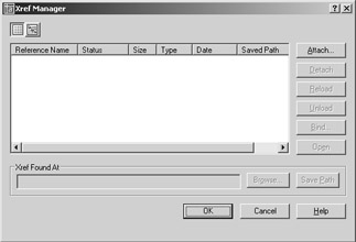
Figure 6.13: The Xref Manager dialog box
Now you're ready to use the Xref Manager:
-
Choose Insert Xref Manager or type XR
to open the Xref Manager dialog box (see Figure 6.13). Instead, you can go directly to this dialog box by choosing Insert External Reference, but it's useful to know where to find the Xref Manager. -
Click the Attach button to open the Select Reference File dialog box. This is a typical Auto- CAD file dialog box complete with a preview window.
-
Locate and select the Unitxref.dwg file, and then click Open to open the External Reference dialog box (see Figure 6.14). Notice that this dialog box looks similar to the Insert dialog box. It offers the same options for insertion point, scale, and rotation.
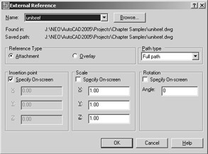
Figure 6.14: The External Reference dialog box -
You'll see a description of the options presented in this dialog box. For now, click OK.
-
Enter 31'-5 ² ,43'-8 ² (metric users enter 957,1330) for the insertion point.
-
After the Unitxref.dwg file is inserted, re-create the same layout of the floor plan you created in the first section of this chapter by copying and mirroring the Unitxref.dwg external reference.
-
Save the Planxref file.
You now have a drawing that looks like the Plan.dwg file you created earlier in this chapter, but instead of using blocks that are detached from their source file, you have a drawing composed of Xrefs. These Xrefs are the actual Unitxref.dwg file, and they are loaded into AutoCAD at the same time that you open the Planxref.dwg file. An icon in the lower-right corner of the AutoCAD window tells you that the current drawing contains Xrefs.
![]() This icon not only alerts you to Xrefs, but it also enables you to open the Xref Manager, as you'll see in the next exercise.
This icon not only alerts you to Xrefs, but it also enables you to open the Xref Manager, as you'll see in the next exercise.
Next, you'll modify the Unitxref.dwg file and see the results in the Planxref.dwg file.
-
LT only To open the Unitxref.dwg file, in the current Planxref file, right-click the unit, and then choose Open Xref from the shortcut menu. You can also enter Xopen
at the command prompt, and then select the unit plan Xref. Warning Xopen and the Open Xref option in the shortcut menu are not available in LT. If you are using LT, choose File Open, and use the Select File dialog box to open the Unitxref.dwg file.
-
Erase the hatch pattern and kitchen outline for the floors, and save the Unitxref.dwg file.
-
Choose Window Planxref.dwg to return to the Planxref.dwg file. Click the Xref icon in the lower-right corner of the AutoCAD window to open the Xref Manager dialog box.
-
Select the Unitxref name in the list box, click Reload, and then click OK. Notice that the units in the Planxref drawing have been updated to include the changes you made to the Unitxref file.
In this exercise, you used Xopen to open an Xref. You can open multiple Xrefs at once by selecting more than one Xref while using the Xopen command.
| Tip | The Open button in the Xref Manager dialog box performs the same function as the Xopen command or the Open Xref option in the shortcut menu. To use this option, select the Xref files from the list box in the Xref Manager dialog box, and then click Open. |
You will want to be aware that when an Xref has been modified, the Xref icon in the lower-right of the AutoCAD window changes to show an exclamation point. This alerts you to changes in an Xref in the current drawing.
![]() Click the Xref icon to open the Xref Manager dialog box. The Xref that has been changed is indicated by a message in the Status column of the list box.
Click the Xref icon to open the Xref Manager dialog box. The Xref that has been changed is indicated by a message in the Status column of the list box.
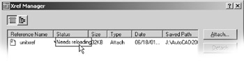
You can then select the Xref that needs to be updated and click the Reload button. You can also right-click the Xref icon and choose the Reload Xref option from the shortcut menu to reload all Xrefs in the drawing without having to open the Xref Manager dialog box.
| |
You can use the Xbind command to import blocks and other drawing components from another file. First, use External Reference Attach to cross-reference a file; type Xbind at the command prompt. In the Xbind dialog box, click the plus sign next to the Xref filename and then select Block. Locate the name of the block you want to import, click the Add button, and click OK. Finally, open the Xref Manager dialog box, select the Xref filename from the list, and click Detach to remove the Xref file. The imported block remains as part of the current file. (See Chapter 12 for details on importing drawing components.) You can also use the Auto- CAD DesignCenter to import items from external files. DesignCenter is described in Chapter 21.
![]() The Tool palettes give you access to frequently used blocks and hatch patterns that reside in other drawings. You can open the Tool palettes by clicking the Tool Palettes icon in the Standard toolbar.
The Tool palettes give you access to frequently used blocks and hatch patterns that reside in other drawings. You can open the Tool palettes by clicking the Tool Palettes icon in the Standard toolbar.
In the standard AutoCAD installations, the Tool palettes are configured with sample blocks and hatch patterns that you can drag and drop into your current drawing. Just select a tab for the Tool palettes that contain the block or pattern you want, and then click and drag the item into your drawing. In the case of hatch patterns, click and drag the pattern into an area that is bounded on all sides by objects. When you are ready to customize the Tool palettes, you do so by using the DesignCenter.
| |
Here you saw how an Xref file is updated in a different way from blocks. Because Xrefs are loaded along with the drawing file that contains them, the containing file, which in this case was the Plan
file, automatically displays any changes made to the Xref when it is opened. Also, you avoid having to update nested blocks, because AutoCAD updates nested Xrefs, as well as non-nested Xrefs. When an Xref is modified while you are editing a file, you are alerted to the change through the Xref icon located in the lower-right corner of the AutoCAD window.
Editing Xrefs and the Files That Contain Them at the Same Time
In the exercise in the " Attaching a Drawing as an External Reference" section, you closed the
Planxref.dwg file, edited the Unitxref.dwg file, and then reopened the Planxref.dwg file. This demonstrates that the Xref is automatically updated when you open the Planxref.dwg file. You could also keep the Planxref.dwg file open while editing the Unitxref.dwg file and then refresh the Unitxref.dwg Xref from the Xref Manager dialog box.
To refresh an Xref, open the Xref Manager dialog box while in the Planxref.dwg file. Highlight the Unitxref name in the list box, click the Reload button, and click OK. Because both the Xref file and the containing file are open, you'll get the message you saw in step 3 of the previous exercise:
File is open for editing. Unable to Demand load, Perform a full read instead? Click OK at this message to update the Xref. By the way, you'll get the same message if someone else is working on the Unitxref file over a network while you're attempting to update the Xref in the Planxref.dwg file. The warning message tells you that an Xref file is currently being edited. See the section " Controlling Xref Settings in the Options Dialog Box" later in this chapter for more information on the Demand Load feature.
| Tip | If you use Xrefs frequently, you might want to place the Insert toolbar permanently in your AutoCAD window. It contains tools for inserting both blocks and Xrefs. To open the Insert toolbar, right-click any toolbar, and then click the Insert check box in the Toolbar dialog box. |
Other Differences between External References and Blocks
Here are a few other differences between Xrefs and inserted blocks that you will want to keep in mind:
-
Any new layers, text styles, or line types brought in with cross-referenced files do not become part of the current file. If you want to import any of these items, you can use the Xbind command (described in Chapter 12).
-
If you make changes to the layers of a cross-referenced file, those changes are not retained when the file is saved, unless you checked the Retain Changes To Xref Layers option in the Open And Save tab of the Options dialog box. This option, found in the External References (Xrefs) group , instructs AutoCAD to remember any layer color or visibility settings from one editing session to the next. In the standard AutoCAD settings, this option is on by default.
Tip Another way to ensure that layer settings for Xrefs are retained is to enter Visretain
at the command prompt. At the New value for VISRETAIN <0>: prompt, enter 1 . -
To segregate layers in Xref files from layers in the current drawing, the Xref file's layers are prefixed with their file's name. A vertical bar separates the filename prefix and the layer name when you view a list of layers in the Layer drop-down list or the Layer Properties Manager dialog box (as in Unitxref wall).
-
You cannot explode Xrefs. You can, however, convert an Xref into a block and then explode it. To do this, click the Bind button in the External Reference dialog box to open another dialog box that offers two ways of converting an Xref into a block. See the section " The External Reference Dialog Box" later in this chapter for more information on this dialog box.
-
If an Xref is renamed or moved to another location on your hard disk, AutoCAD won't be able to find that file when it opens other files to which the Xref is attached. If this happens, you must use the Browse option in the External Reference dialog box to tell AutoCAD where to find the cross-reference file.
Warning Take care when relocating an Xref file with the Browse button. The Browse button can assign a file of a different name to an existing Xref as a substitution.
-
Xref files are especially useful in workgroup environments in which several people are working on the same project. For example, one person might be updating several files that are inserted into a variety of other files. Using blocks, everyone in the workgroup would have to be notified of the changes and would have to update all the affected blocks in all the drawings that contained them. With cross-referenced files, however, the updating is automatic; so you avoid confusion about which files need their blocks updated.
| |
Although these exercises demonstrate how Xrefs work, you aren't limited to using them in the way shown here. Perhaps one of the more common ways of using Xrefs is to combine a single floor plan with different title block drawings, each with its own layer settings and title block information. In this way, single-drawing files can be reused in several drawing sheets of a final construction document set. This helps keep data consistent across drawings and reduces the number of overall drawings needed.
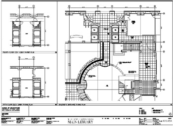
This is exactly how Xrefs were used in the San Francisco Main Library drawings. One floor-plan file contained most of the main information for that floor. The floor plan was then used as an Xref in another file that contained the title block, as well as additional information such as furnishings or floor finish reference symbols. Layer visibility was controlled in each title block drawing so only the data related to that drawing appeared.
Multiple Xref files were also used by segregating the structural column grid layout drawings from the floor- plan files. In other cases, portions of plans from different floors were combined into a single drawing by using Xrefs, as shown here.
| |
Other External Reference Options
There are many other features unique to external reference files. Let's briefly look at some of the other options in the Xref Manager dialog box.
Options in the Xref Manager Dialog Box
The following options are found in the main Xref Manager dialog box, shown in Figure 6.13 earlier in this chapter. All but the Attach option are available only when an Xref is present in the current drawing and its name is selected from the list of Xrefs shown in the main part of the dialog box.
Attach Opens the Select Reference dialog box, in which you can select a file to attach and set the parameters for the attachment.
Detach Detaches an Xref from the current file. The file is then completely disassociated from the current file.
Reload Restores an unloaded Xref.
Unload Similar to Detach but maintains a link to the Xref file so that it can be quickly reattached. This has an effect similar to freezing a layer and can reduce redraw , regeneration, and file- loading times.
Bind Converts an Xref into a block. Bind offers two options: Bind (again) and Insert. Bind's Bind option maintains the Xref's named elements (layers, line types, and text and dimension styles) by creating new layers in the current file with the Xref's filename prefix (see Chapter 12). The Insert option does not attempt to maintain the Xref's named elements but merges them with named elements of the same name in the current file. For example, if both the Xref and the current file have layers of the same name, the objects in the Xref are placed in the layers of the same name in the current file.
ACAD only Open Lets you open an Xref. Select the Xref from the list and then click Open. The Xref opens in a new window when you close the Xref Manager dialog box. This option is not available in AutoCAD LT.
Browse Opens the Select New Path dialog box from which you can select a new file or a location for a selected Xref.
Save Path Saves the file path displayed in the Xref Found At input box.
List View/Tree View These two buttons are in the upper-left corner of the Xref Manager dialog box. They let you switch between a List view of your Xrefs and a hierarchical Tree view. The Tree view can be helpful in determining how Xrefs are nested. The Xref list works like other Windows lists and can be sorted by name, status, size, type, date, or path. To sort by name, for example, click the Reference Name button at the top of the list.
The External Reference Dialog Box
The External Reference dialog box, shown in Figure 6.14 earlier in this chapter, offers these options:
Browse Opens the Select Reference File dialog box to enable you to change the file you are importing as an Xref.
Attachment Causes AutoCAD to include other Xref attachments that are nested in the selected file.
Overlay Causes AutoCAD to ignore other Xref attachments that are nested in the selected file. This avoids multiple attachments of other files and eliminates the possibility of circular references (referencing the current file into itself through another file).
Path Type Xref files can be located anywhere on your system, including network servers. For this reason, links to Xrefs can be easily lost either by moving them or rearranging file locations. To help you manage Xrefs, the Path Type option offers three options for locating Xrefs: Full Path, Relative Path, and No Path. Full Path retains the current full path. Relative Path maintains paths in relation to the current drawing. The current drawing must be saved before using the Relative Path option. The No Path option is for drawings in which Xrefs are located in the same folder as the current drawing or in the Support file search path that is specified in the Files tab of the Options dialog box (choose Tools Options).
Specify On-Screen Appears in three places. It gives you the option to enter insertion point, scale factors, and rotation angles within the dialog box or in the Command window, in a way similar to inserting blocks. If you clear this option for any of the corresponding parameters, the parameters change to allow input. If they are selected, you are prompted for those parameters after you click OK to close the dialog box. With all three Specify On-Screen check boxes cleared, the Xref is inserted in the drawing using the settings indicated in the dialog box.
Clipping Xref Views and Improving Performance
Xrefs are frequently used to import large drawings for reference or backgrounds. Multiple Xrefs, such as a floor plan, column grid layout, and site plan drawing, might be combined into one file. One drawback to multiple Xrefs in earlier versions of AutoCAD is that the entire Xref is loaded into memory, even if only a small portion of the Xref is used for the final plotted output. For computers with limited resources, multiple Xrefs could slow the system to a crawl.
AutoCAD 2005 offers two tools that help make display and memory use more efficient when using Xrefs: the Xclip command and the Demand Load option in the Options dialog box.
Clipping Views
The Xclip command enables you to clip the display of an Xref or a block to any shape you want, as shown in Figure 6.15. For example, you might want to display only an L-shaped portion of a floor plan to be part of your current drawing. Xclip lets you define such a view. To access the command, choose Modify Clip Xref.
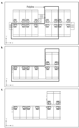
Figure 6.15: The first panel shows a polyline outline of the area to be isolated with Xclip. The second panel shows how the Xref appears after Xclip is applied. The last panel shows a view of the plan with the polyline's layer turned off.
You can clip blocks and multiple Xrefs as well. And you can specify a front and back clipping distance so that visibility of objects in 3D space can be controlled. You can define a clip area by using polylines or spline curves, although curve-fitted polylines will revert to decurved polylines. (See Chapter 13 for more on polylines and spline curves.)
Controlling Xref Settings in the Options Dialog Box
The External References (XRefs) group in the Open And Save tab of the Options dialog box offers some tools to help you manage memory use and other features related to Xrefs. If you're working on large projects with others in a workgroup, you'll want to be aware of these settings and what they do.
The Demand Load Xrefs drop-down list offers three settings: Disabled, Enabled, and Enabled With Copy. Demand Load is enabled by default in the standard AutoCAD drawing setup. Besides reducing the amount of memory an Xref consumes, Demand Load also prevents other users from editing the Xref while it is being viewed as part of your current drawing. This is done to help aid drawing version control and drawing management. The Enabled With Copy option creates a copy of the source Xref file and then uses the copy, thereby enabling other AutoCAD users to edit the source Xref file.
Demand loading improves performance by loading only the parts of the referenced drawing that are needed to regenerate the current drawing. You can set the location for the Xref copy in the Files tab of the Options dialog box under Temporary External Reference File Location.
Two other options are also available in the Options dialog box:
Retain Changes To Xref Layers Instructs AutoCAD to remember any layer color or visibility settings of Xrefs from one editing session to the next. In the standard AutoCAD settings, this option is on by default.
Allow Other Users To Refedit Current Drawing Lets others edit the current drawing by using the Modify Xref And Block Edit Edit Reference command (Refedit). You'll learn about this command in the next section.
EAN: 2147483647
Pages: 261
- ERP System Acquisition: A Process Model and Results From an Austrian Survey
- Enterprise Application Integration: New Solutions for a Solved Problem or a Challenging Research Field?
- Intrinsic and Contextual Data Quality: The Effect of Media and Personal Involvement
- Healthcare Information: From Administrative to Practice Databases
- Relevance and Micro-Relevance for the Professional as Determinants of IT-Diffusion and IT-Use in Healthcare