Understanding the Boundary Hatch Options
The Boundary Hatch And Fill dialog box offers many other options that you didn't explore in the previous exercises. For example, instead of selecting the area to be hatched by clicking a point, you can select the actual objects that bound the area you want to hatch by using the Select Objects button. The Swatch box opens the Hatch Pattern Palette dialog box, which lets you select a predefined hatch pattern from a graphic window.
The Hatch Pattern Palette dialog box has several tabs that further divide the types of hatch patterns into four categories: ANSI, ISO, Other Predefined, and Custom. The Custom tab is empty until you create your own set of custom hatch patterns. See Chapter 19 for details on how to create custom hatch patterns.
Other options in the right column of the Boundary Hatch And Fill dialog box include Remove Islands, View Selections, and Inherit Properties:
Remove Islands Lets you remove a bounded area or "island" within the area to be hatched. An example of this is the toilet seat in the bathroom. This option is available only when you select a hatch area by using the Pick Points option and an island has been detected .
View Selections Temporarily closes the dialog box and then highlights the objects that have been selected as the hatch boundary by AutoCAD.
Inherit Properties Lets you select a hatch pattern from an existing one in the drawing. This is helpful when you want to apply a hatch pattern that is already used, but you do not know its name or its scale, rotation, or other properties.
At the very bottom of the column of options is the Composition button group . This option lets you determine whether the hatch pattern being inserted is associative or nonassociative. As discussed earlier, an associative hatch pattern automatically changes to fill its boundary whenever that boundary is stretched or edited.
Using the Advanced Hatch Options
AutoCAD's Boundary Hatch command has a fair amount of "intelligence." As you saw in an earlier exercise, it was able to detect not only the outline of the floor area, but also the outline of the toilet seat that represents an island within the pattern area. If you prefer, you can control how AutoCAD treats these island conditions and other situations by selecting options available when you click the Advanced tab in the Boundary Hatch And Fill dialog box. In addition to controlling the Island Detection feature of hatch patterns, the Advanced tab lets you fine-tune other aspects of hatch pattern creation.
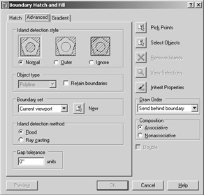
Island Detection Style
The Island Detection Style button group at the top of the dialog box controls how nested boundaries affect the hatch pattern. The graphics in this button group show examples of the effect of the selected option. The Island Detection Style options include the following:
Normal Causes the hatch pattern to alternate between nested boundaries. The outer boundary is hatched; if there is a closed object within the boundary, it is not hatched. If another closed object is inside the first closed object, that object is hatched. This is the default setting.
Outer Applies the hatch pattern to an area defined by the outermost boundary and a closed objects within that boundary. Any boundaries nested within that closed object are ignored.
Ignore Supplies the hatch pattern to the entire area within the outermost boundary, ignoring any nested boundaries.
Object Type
The Boundary Hatch command can also create an outline of the hatch area by using one of two objects: 2D regions , which are like 2D planes, or polyline outlines. Boundary Hatch creates such a poly- line boundary temporarily, to establish the hatch area. These boundaries are automatically removed after the hatch pattern is inserted. If you want to retain the boundaries in the drawing, make sure the Retain Boundaries check box is selected. Retaining the boundary can be useful if you know you will be hatching the area more than once or if you are hatching a fairly complex area.
| Tip | Retaining a hatch boundary is useful if you want to know the hatched area's dimensions in square inches or feet, because you can find the area of a closed polyline by using the List command. See "Displaying Data in a Text Window" in Chapter 2 for more on the List command. |
| Tip | The Boundary command creates a polyline outline or region within a selected area. It works much like the Boundary Hatch command but does not add a hatch pattern. |
Boundary Set Options
The Boundary Hatch feature is view-dependent; that is, it locates boundaries based on what is visible in the current view. If the current view contains a lot of graphic data, AutoCAD can have difficulty finding a boundary or can be slow in finding a boundary. If you run into this problem, or if you want to single out a specific object for a point selection boundary, you can further limit the area that AutoCAD uses to locate hatch boundaries by using the Boundary Set options.
New Lets you select the objects from which you want AutoCAD to determine the hatch boundary, instead of searching the entire view. The screen clears and lets you select objects. This option discards previous boundary sets. It is useful for hatching areas in a drawing that contain many objects that you do not want to include in the hatch boundary.
Current Viewport Tells you that AutoCAD will use the current view to determine the hatch boundary. After you select a set of objects by using the New button, you also see Existing Set as an option in this drop-down list. You can then use this drop-down list to choose the entire view or the objects you select for the hatch boundary.
The Boundary Set options are designed to give you more control over the way a point selection boundary is created. These options have no effect when you use the Select Objects button to select specific objects for the hatch boundary.
Island Detection Method
You might have noticed that the Boundary Hatch command did not place a hatch pattern on the toilet seat. This is because the Island Detection feature was turned on. The toilet seat is like an island within the hatch area. The Island Detection Method radio buttons let you control how islands such as the toilet seat are detected. The Flood option detects islands and hatches around them. The Ray Casting option determines the boundary outline by first looking for the nearest object to your pick point and then tracing along that object in a counterclockwise direction.
Gap Tolerance
In versions of AutoCAD prior to 2005, you could apply a hatch pattern only to an area that was entirely closed; in other words, there could not be any gaps in the area you wanted to hatch. Auto- CAD 2005 offers the Gap Tolerance option that lets you hatch an area that is not completely enclosed . The Gap Tolerance value sets the maximum gap size in an area that you want to hatch. You can use a value from 0 to 5000.
Draw Order
Hatch patterns have the capability to cover or draw over existing graphics. This is especially true of solid-fill or gradient hatch patterns. The new Draw Order option lets you control whether your hatch pattern is drawn over existing objects or whether it is placed "underneath" existing objects. For a detailed description of the Draw Order option, see " Space Planning and Hatch Patterns" later in this chapter.
Using Gradient Shading
ACAD only You might have noticed that one of the hatch patterns offered is a solid. The solid hatch pattern lets you apply a solid color instead of a pattern to a bounded area. AutoCAD also offers a set of gradient patterns that let you apply a color gradient to an area.
You can apply a gradient to an area by using the same method you used to apply a hatch pattern, but instead of using the Hatch tab of the Boundary Hatch And Fill dialog box, you use the Gradient tab to select a gradient pattern.
| Warning | The Gradient Shading feature is not available in AutoCAD LT. |
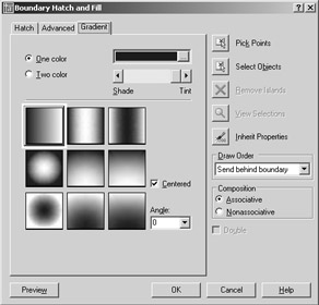
Choosing a Gradient Color
Instead of offering hatch patterns, the Gradient tab offers a variety of gradient patterns. It also lets you control the color of the gradient. For example, if you want to set the gradient between shades of blue, you can click the One Color radio button and then double-click the blue color swatch at the top of the dialog box.
When you double-click the color swatch, the Select Color dialog box appears, offering a palette of True Color options.
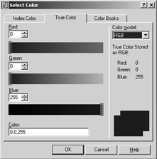
You can then select the color you want for the gradient. On the Gradient tab of the Boundary Hatch And Fill dialog box, the Shade/Tint slider just below the color swatch lets you control the shade of the single-color gradient.
Using Two Colors
You can choose a gradient that transitions between shades of a single color by using the One Color radio button, or you can transition between two entirely different colors by selecting the Two Color radio button. When you select Two Color, the slider to the right of the Two Color option changes to a color swatch. You can double-click the swatch or click the ellipses button to the right of the swatch to open the Select Color dialog box.
Selecting Gradient Patterns
Just below the One Color and Two Color options are the gradient pattern options. You can choose from nine patterns, plus you can select an angle for the pattern from the Angle drop-down list box. The Center option places the center of the gradient at the center of the area selected for the pattern.
To place a gradient pattern, select a set of objects or a point within a bounded area, just as you would for a hatch pattern. You can then click the Preview button to preview your hatch pattern, or you can click OK to apply the gradient to the drawing.
Tips for Using the Boundary Hatch
Here are a few tips on using the Boundary Hatch feature:
-
Watch out for boundary areas that are part of a very large block. AutoCAD examines the entire block when defining boundaries. This can take time if the block is quite large. Use the Boundary Set option to "focus in" on the set of objects you want AutoCAD to use for your hatch boundary.
-
The Boundary Hatch feature is view-dependent; that is, it locates boundaries based on what is visible in the current view. To ensure that AutoCAD finds every detail, zoom in to the area to be hatched.
-
If the area to be hatched will be very large yet will require fine detail, first outline the hatch area by using a polyline. (See Chapter 13 for more on polylines.) Then use the Select Objects option in the Boundary Hatch And Fill dialog box to select the polyline boundary manually, instead of depending on Boundary Hatch to find the boundary for you.
-
Consider turning off layers that might interfere with AutoCAD's ability to find a boundary.
For example, in the previous exercise, you could turn off the Door layer and then use Pick Points to locate the boundary of the hatch pattern.
-
Boundary Hatch works on nested blocks as long as the nested block entities are parallel to the current UCS and are uniformly scaled in the x - and y-axes.
| |
Another tool to help you edit hatch patterns is Match Properties, which is similar to Format Painter in the Microsoft Office suite. This tool lets you change an existing hatch pattern to match another existing hatch pattern. Here's how to use it:
-
 Click the Match Properties tool in the Standard toolbar.
 -
Click the source hatch pattern you want to copy.
-
Click the target hatch pattern you want to change. The target pattern changes to match the source pattern.
The Match Properties tool transfers other properties as well, such as layer, color, and line-type settings. You can select the properties that are transferred by opening the Property Settings dialog box.
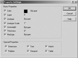
To open this dialog box, type S ![]() after selecting the object in step 2, or right-click and choose Settings from the shortcut menu. You can then select the properties you want to transfer from the options shown. All the properties are selected by default. Note that text and dimension style settings can also be transferred. You'll learn more about text and dimension styles in Chapters 8 and 9.
after selecting the object in step 2, or right-click and choose Settings from the shortcut menu. You can then select the properties you want to transfer from the options shown. All the properties are selected by default. Note that text and dimension style settings can also be transferred. You'll learn more about text and dimension styles in Chapters 8 and 9.
| |
Space Planning and Hatch Patterns
Suppose you are working on a plan within which you are constantly repositioning equipment and furniture, or you are in the process of designing the floor covering. You might be a little hesitant to place a hatch pattern on the floor because you don't want to have to rehatch the area each time you move a piece of equipment or change the flooring. You have two options in this situation: you can use the Boundary Hatch's associative capabilities to include the furnishings in the boundary set, or you can use the Display Order feature.
Using Associative Hatch
Associative Hatch is the most straightforward method. Make sure the Associative option is selected in the Boundary Hatch And Fill dialog box and include your equipment or furniture in the boundary set. You can do this by using the Select Objects option in the dialog box.
After the pattern is in place, the hatch pattern automatically adjusts to its new location when you move the furnishings in your drawing. One drawback, however, is that AutoCAD attempts to hatch the interior of your furnishings if they cross over the outer boundary of the hatch pattern. Also, if any boundary objects are erased or exploded, the hatch pattern no longer follows the location of your furnishings. To avoid these problems, you can use the method described in the next section.
Overlapping Objects with Draw Order
The Draw Order feature lets you determine how objects overlap each other. In the space-planning example, you can create furniture by using a solid hatch to indicate horizontal surfaces (see Figure 6.12). You can then place the furniture "on top" of a floor-covering pattern, and the pattern will be covered and hidden by the furniture. Here's how to do that. (These steps are not part of the regular exercises of this chapter. They are shown here as general guidelines when you need to use the Draw Order feature.)
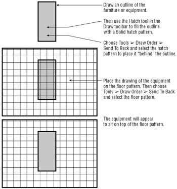
Figure 6.12: Using Draw Order to create an overlapping effect over a hatch pattern
-
Draw the equipment outline and make sure the outline is a closed polygon.
-
Start the Hatch tool described earlier in this chapter to place a Solid hatch pattern inside the equipment outline.
-
Select the Advanced tab in the Boundary Hatch And Fill dialog box and make sure that Send Behind Boundary is selected in the Draw Order drop-down list.
-
Complete the rest of the hatch pattern.
-
After you've finished placing the hatch, turn the outline and solid hatch into a block, or use the Group command to group them together.
-
Choose Tools Draw Order Bring To Front, and select the equipment. When you are done, the equipment will "cover" the floor hatch pattern (see the bottom panel in Figure 6.12).
After you take these steps, you can place the equipment over a hatched floor pattern, and the equipment will appear to rest on top of the pattern. If you create a floor pattern after you create the equipment, choose Tools Draw Order Send To Back to move the pattern to the back of the display order. You can also change the display order of objects relative to other objects.
The Draw Order options are all part of the Draworder command. As an alternative to the dialog box, you can type Draworder ![]() at the command prompt and then enter an option at the Draworder prompt:
at the command prompt and then enter an option at the Draworder prompt:
Enter object ordering option [Above object/Under object/Front/Back] <Back>:
For example, the equivalent of choosing Tools Draw Order Send To Back is entering Draworder ![]() B
B ![]() .
.
If you need to "white out" an area of a hatch pattern to make text more readable, you can use a solid hatch along with the Display Order option to block out areas behind text.
| Tip | Draworder settings are maintained through blocks and Xrefs. |
You've had a detailed look at hatch patterns and fills in this section. Remember that you can also use the Tool palettes to help organize and simplify access to your favorite hatch patterns, or just use the patterns already available in the Tool palettes. The patterns found in the Tool palettes can be edited and manipulated in the same way as described in this chapter. If you want to know how to make full use of the Tool palettes, check out the discussion on the AutoCAD DesignCenter in Chapter 21.
EAN: 2147483647
Pages: 261