Assembling the Parts
One of the best time-saving features of AutoCAD is its ability to quickly duplicate repetitive elements in a drawing. In this section, you'll assemble the drawings you've been working on into the complete floor plan of a fictitious apartment project. This will demonstrate how you can quickly and accurately copy your existing drawings in a variety of ways.
Start by creating a new file for the first floor:
-
Create a new file named Plan to contain the drawing of the apartment building's first floor. This is the file you will use to assemble the unit plans into an apartment building. If you want to use a template file, use the Acad.dwt template file. Metric users can use the Acadiso.dwt template file. (These are AutoCAD template files that appear in the Select Template dialog box when you select File > New).
-
Set the Units style to Architectural (choose Format Units).
-
Set up the drawing for a 1 / 8 ² = 1'-0 ² scale on a 24 ² 18 ² drawing area (choose Format Drawing Limits). If you look at Table 3.2 in Chapter 3, you'll see that such a drawing requires an area 2304 units wide 1728 units deep. Metric users should set up a drawing at 1:100 scale on an A2 sheet size . If you look at Table 3.4, you'll see that your drawing area should be 5940 cm 4200 cm.
-
Create a layer called Plan1 and make it the current layer.
-
In the Drafting Settings dialog box, set the Snap mode to 1 , and set the grid to 8 ' , which is the distance required to display 1 ² divisions in a 1 / 8 ² = 1'-0 ² scale drawing. Metric users can set the Grid mode to 250 .
-
Turn on the grid.
-
Choose View Zoom All or type Z
 A to get an overall view of the drawing area.
Now you're ready to start building a floor plan of the first floor from the Unit plan you created in the previous chapter. You'll start by creating a mirrored copy of the apartment plan:
-
Make sure Running Osnaps are turned off, and then insert the Unit.dwg drawing at coordinate 31'-5 ² ,43'-8 ² (957,1330 for metric users). Accept the default.
Tip If you prefer, you can specify the insertion point in the Insert dialog box by removing the checkmark from the Specify On-Screen check box. The Input options in the dialog box then become available to receive your input.
-
Zoom in to the apartment unit plan.
-
 Click Mirror on the Modify toolbar, select the unit plan, and press .
 -
At the Specify first point of the mirror line: prompt, Shift+right-click the mouse and choose From.
-
Shift+right-click again and choose Endpoint.
-
Select the endpoint of the upper-right corner of the apartment unit, as shown in Figure 6.1.
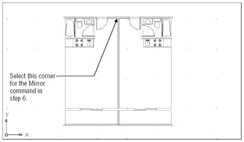
Figure 6.1: The unit plan mirrored -
Enter @2.5<0
. Metric users should enter @6.5<0 . A rubber-banding line appears, indicating the mirror axis. -
Turn on the Ortho mode and select any point to make the mirror axis point in a vertical orientation.
-
At the Delete Source Objects? [Yes/No] <N>: prompt, press
. You will get a 5 ² wall thickness between two studio units. Your drawing should be similar to Figure 6.1.
Select this corner for the Mirror command in step 6.
You now have a mirror-image copy of the original plan in the exact location required for the overall plan. Now make some additional copies for the opposite side of the building:
-
Press
to reissue the Mirror command and select both units. -
Use the From Osnap option again, and, using Endpoint Osnap, select the same corner you selected in step 6.
-
Enter @24<90 to start a mirror axis 24 ² directly above the selected point. Metric users should enter @61<90 .
-
With the Ortho mode on, select a point so that the mirror axis is exactly horizontal.
-
Press
to keep the original units and complete the mirror operation.
With the tools you've learned about so far, you've quickly and accurately set up a fairly good portion of the floor plan. Continue with the next few steps to "rough-in" the main components of the floor:
-
Choose View Zoom Extents or type Z
E to get a view of the four plans. You can also use the Extents tool on the Zoom Window tool flyout . The Extents option forces the entire drawing to fill the screen at the leftmost side of the display area. Your drawing will look like Figure 6.2. 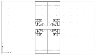
Figure 6.2: The unit plan, duplicated four timesTip If you happen to insert a block in the wrong coordinate location, you can use the Properties palette to change the insertion point for the block.
-
Copy the four units to the right at a distance of 28'-10 ² (878 cm for metric users), which is the width of two units from centerline to centerline of walls.
-
Insert the lobby at coordinate 89'-1 ² ,76'-1 ² (2713,2318 for metric users).
-
Copy all the unit plans to the right 74'-5 ² (2267 cm for metric users), the width of four units plus the width of the lobby.
-
Choose View Zoom All or type Z
A to view the entire drawing, which should look like Figure 6.3. You can also use the Zoom All tool on the Zoom Window flyout. 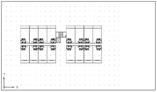
Figure 6.3: The Plan drawing -
Choose File Save to save this Plan.dwg file to disk.
EAN: 2147483647
Pages: 261