Developing Your Drawing
As mentioned briefly in Chapter 3, when using AutoCAD, you first create the basic geometric forms used in your drawing; then you refine them. In this section, you will create two drawings ”the studio apartment unit and the lobby ”that demonstrate this process in more detail.
First, you will construct a typical studio apartment unit by using the drawings you have created thus far. In the process, you will explore the use of lines as reference objects.
You will also further examine how to use existing files as blocks. In Chapter 4, you inserted a file into another file. There is no limit to the size or number of files you can insert. As you might already have guessed, you can also nest files and blocks; that is, you can insert blocks or files within other blocks or files. Nesting can help reduce your drawing time by enabling you to build one block out of smaller blocks. For example, you can insert your door drawing into the bathroom plan. In turn , you can insert the bathroom plan into the studio unit plan, which also contains doors. Finally, you can insert the unit plan into the overall floor plan for the studio apartment building.
Importing Settings
In this exercise, you will use the Bath file as a prototype for the studio unit plan. However, you must make a few changes to it first. After the changes are made, you will import the bathroom and thereby import the layers and blocks contained in the bathroom file.
As you go through this exercise, observe how the drawings begin to evolve from simple forms to complex, assembled forms.
On the CD Use these steps to modify the Bath file:
-
First, open the Bath file. If you skipped drawing the Bath file in Chapter 4, use the file named 04c-bath.dwg (or 04c-bath-metric.dwg ) from the companion CD.
-
Use the Base command and select the upper-left corner of the bathroom as the new base point for this drawing, so you can position the Bath file more accurately.
-
Save the Bath file. If you use the file from the CD, choose File Save As and save it as Bath .
-
Choose File Close to close the Bath drawing.
Next , you will create a new file. But this time, instead of using the Start From Scratch or Use A Template option in the Create New Drawing dialog box, you'll try the Use A Wizard option:
-
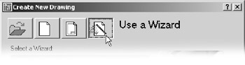
Choose File New to open the Create New Drawing dialog box.
-
Click the Use A Wizard button to display two options below the drop-down list: Quick Setup and Advanced Setup.
-
Choose Quick Setup and click OK to open the QuickSetup dialog box.
-
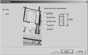
Click the Architectural radio button. Metric users should use the default Decimal units.
-
Click Next to display the Area settings.
-
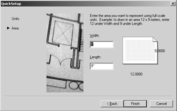
Enter 528 in the Width text box and 408 in the Length box. These are the appropriate dimensions for an 8 ½ ² 11 ² drawing at ¼ ² = 1 ¢ -0 ² scale. Metric users should enter 1485 for the width and 1050 for the length. This is the work area for a 1:50 scale drawing on an A4 sheet.
-
Click Finish.
-
Choose Tools Drafting Settings to set the snap spacing to 1 ² and the grid spacing to 48 ² . The grid spacing setting will change to 4 ¢ . This sets the grid spacing to display the equivalent of 1 ² intervals for a ¼ ² = 1 ¢ -0 ² scale drawing. Metric users should set the snap spacing to 1 and the grid spacing to 120 .
Tip If you need to find out the equivalent drawing area for a given sheet size and scale, see Chapter 3.
In prior sessions, you opened a blank file and chose Format Units And Format Drawing Limits to set up your drawing. This time, you used the QuickSetup Wizard to accomplish the same thing. In fact, the QuickSetup Wizard does nothing more than combine the Format Units And Format Drawing Limits options into one dialog box.
Now let's continue by laying out a typical studio unit. You'll also discover how importing a file also imports a variety of drawing items such as layers and line types. Follow these steps:
-
Begin the unit by drawing two rectangles, one 14 ¢ wide by 24 ¢ long, and the other 14 ¢ wide by 4 ¢ long. Metric users should make the rectangles 426 cm wide by 731 cm long and 426 cm wide by 122 cm long. Place them as shown in Figure 5.8. The large rectangle represents the interior of the apartment unit, and the small rectangle represents the balcony . The size and location of the rectangles are indicated in the figure.
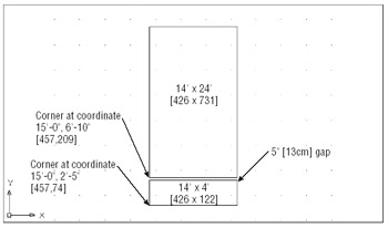
Figure 5.8: The apartment unit interior and balcony. Metric locations and dimensions are shown in brackets.Tip If you used the Rectangle tool to draw the interior and balcony of the apartment unit, make sure you use the Explode tool on the Modify toolbar to explode the rectangles. The Rectangle tool draws a polyline rectangle instead of simple line segments, so you need to explode the rectangle to reduce it to its component lines. You'll learn more about polylines in Chapter 13.
-
 Click the Insert Block tool on the Draw toolbar to open the Insert dialog box.
 -
Click the Browse button, and locate and select the bathroom drawing by using the Select Drawing File dialog box. Then click Open.
Tip If you are using the 04c-bath.dwg file from the CD, do the following: After performing step 3, change the name that appears in the Block text box to Bath instead of 04c-bath before you click OK in step 4. This gives the inserted file a block name of Bath, even though its originating filename is 04c-bath .
-
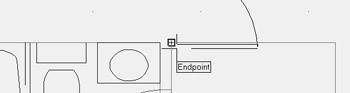
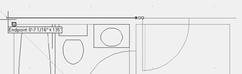
Click OK in the Insert dialog box, and then click the upper-left corner of the unit's interior as the insertion point (see Figure 5.9). You can use the Endpoint Osnap to place the bathroom accurately. Use a scale factor of 1.0 and a rotation angle of 0 °.
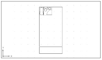
Figure 5.9: The unit after the bathroom is insertedTip Because the Running Osnaps have not been set up in this file, you need to use the Osnap shortcut menu (Shift+right- click) to access the Endpoint Osnap. You can set up the Running Osnaps to take advantage of AutoCAD's AutoSnap functions by right-clicking the Osnap box in the status bar. Set the Running Osnaps as described in Chapter 3.
-
Assign the two rectangles that you drew earlier to the Wall layer. To do this, select the two rectangles so they are highlighted, and then open the Layer drop-down list in the Properties tool- bar and select Wall. Press the Esc key twice to clear the selection.
Tip You can also use the Match Properties tool on the Standard toolbar to change layer settings of an object to those of another object in the drawing. See Chapter 6.
By inserting the bathroom, you imported the layers and blocks contained in the Bath file. You were then able to move previously drawn objects to the imported layers. If you are in a hurry, this can be a quick way to duplicate layers that you know exist in another drawing. This method is similar to using an existing drawing as a template, but it enables you to start work on a drawing before deciding which template to use.
| Warning | If two drawings contain the same layers and blocks, and one of these drawings is imported into the other, the layer settings and block definitions of the current file will take priority over those of the imported file. This is important to remember when the layer settings and block definitions are different in the two files. |
| |
As explained in Chapter 4, you can use the External Reference (Xref) Attach option to use another file as a background, or Xref, file. Xref files are similar to blocks except that they do not become part of the current drawing's database; nor do the settings from the cross-referenced file automatically become part of the current drawing.
If you want to import layers, line types, text styles, and so forth from an Xref file, you must use the Xbind command, which you will learn more about as you work through this book. Xbind enables you to attach dimension style settings (discussed in Chapter 9 and in Appendix A), layers, line types, or text styles (discussed in Chapter 8) from a cross-referenced file to the current file. You can also use Xbind to turn a cross- referenced file into an ordinary block, thereby importing all the new settings contained in that file.
See Chapter 12 for a more detailed description of how to use the External References (Xref) and Xbind commands.
Another tool for importing settings is the AutoCAD DesignCenter. You'll learn about the DesignCenter in Chapter 21.
| |
Using Osnap Tracking to Place Objects
You will draw lines in the majority of your work, so it is important to know how to manipulate lines to your best advantage. In this section, you will look at some of the more common ways to use and edit these fundamental drawing objects. The following exercises show you the process of drawing lines, rather than just how individual commands work. While you're building walls and adding doors, you'll get a chance to become more familiar with Polar Tracking and Osnap Tracking.
Roughing In the Line Work
The bathroom you inserted in the preceding section has only one side of its interior walls drawn. (Walls are usually shown by double lines.) In this next exercise, you will draw the other side. Rather than trying to draw the wall perfectly the first time, you will "sketch" in the line work and then in the next section clean it up, in a way similar to manual drafting.
Use these steps to rough in the wall lines:
-
Zoom into the bathroom so that the entire bathroom and part of the area around it are displayed, as in Figure 5.10.
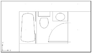
Figure 5.10: The enlarged view of the bathroomTip You might notice that some of the arcs in your bathroom drawing are not smooth. Don't be alarmed; this is how Auto- CAD displays arcs and circles in enlarged views. The arcs will be smooth when they are plotted. If you want to see them now as they are stored in the file, you can regenerate the drawing by typing Regen
 at the command prompt. Chapter 6 discusses regeneration in more detail.
 -
Select Wall from the Layer drop-down list in the Properties toolbar to make Wall the current layer.
-
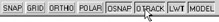
Make sure that the Otrack and Osnap buttons on the status bar are pressed, indicating that Osnap Tracking and Object Snap are turned on.
-
Choose Draw Line or type L
. -
At the Specify first point: prompt, move your cursor over the lower-right corner of the bathroom so that the Endpoint Osnap marker appears, but don't click it. As you move the cursor downward, the tracking vector appears. (If the tracking vector doesn't appear at first, move your cursor over the corner again until it does appear.)
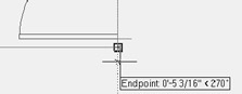
Tip Remember that a little cross appears at the Osnap location telling you that the Osnap Tracking has "locked on"to that location.
-
With the tracking vector visible, point the cursor directly downward from the corner and then type 5
. Metric users should type 13 . Now a line starts 5 ² (or 13 cm) below the lower-right corner of the bathroom. -
Continue the line horizontally to the left, to slightly cross the left wall of the apartment unit, as illustrated in the top image in Figure 5.11. Press
. 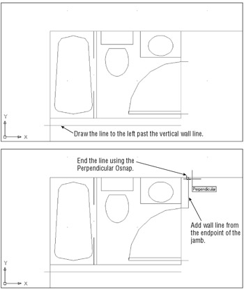
Figure 5.11: The first wall line and the wall line by the door -
Draw another line upward from the endpoint of the top door jamb to meet the top wall of the unit (see the second image in Figure 5.11). Use the Polar Tracking mode and the Perpendicular Osnap to pick the top wall of the unit. This causes the line to end precisely on the wall line in perpendicular position, as in the bottom image in Figure 5.11.
Tip You can also use the Perpendicular Osnap override to draw a line perpendicular to a non-orthogonal line ”one at a 45 ° angle, for instance.
-
Draw a line connecting the two door jambs. Then assign that line to the Ceiling layer (see the first panel in Figure 5.12).
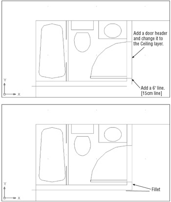
Figure 5.12: The corner of the bathroom wall and the filleted wall around the bathroom -
Draw a line 6 ² downward from the endpoint of the door jamb nearest the corner (see the first panel in Figure 5.12).
| |
The Osnap Tracking vector comes into play only after you've placed an Osnap marker on a location, in this case, the corner of the bathroom. It won't appear at any other time. If you have both Running Osnaps and Osnap Tracking turned on, you'll get the tracking vector every time the cursor lands on an Osnap location. This can be a bit confusing to novice users, so you might want to use Osnap Tracking sparingly until you become more comfortable with it.
And because Polar Tracking also uses a tracking vector, you can get the two confused . Remember that Polar Tracking lets you point the cursor in a specific direction while selecting points. If you're an experienced AutoCAD user , you can think of it as a more intelligent Ortho mode. On the other hand, Osnap Tracking lets you align points to Osnap locations. Experienced AutoCAD users can think of Osnap Tracking as a more intelligent XYZ filter option.
| |
In the previous exercise, Osnap Tracking mode enabled you to specify a starting point of a line at an exact distance from the corner of the bathroom. In step 6, you used the Direct Distance method for specifying distance and direction.
| Tip | If you prefer, you can also choose From on the Osnap shortcut menu, and then open the shortcut menu again and select Endpoint. Select the corner and enter a polar coordinate such as @5<-90 to accomplish the same task as this exercise. |
Cleaning Up the Line Work
You've drawn some of the wall lines, approximating their endpoint locations. Next you will use the Fillet command to join lines exactly end to end and then import the Kitchen drawing.
Follow these steps to join the lines:
-
 Click the Fillet tool on the Modify toolbar.
 -
Type R
to make sure that the fillet radius is set to 0. Tip The Chamfer command performs a similar function to the Fillet command. Unlike Fillet, the Chamfer command enables you to join two lines with an intermediate beveled line rather than with an arc. Chamfer can be set to join two lines at a corner in exactly the same manner as Fillet.
-
Next, fillet the two lines by picking the vertical and horizontal lines, as indicated in the second panel of Figure 5.12. Notice that these points lie on the portion of the line you want to keep. Your drawing will look like the second panel of Figure 5.12.
-
Fillet the bottom wall of the bathroom with the left wall of the unit, as shown in Figure 5.13. Make sure the points you pick on the wall lines are on the side of the line you want to keep, not the side you want trimmed .
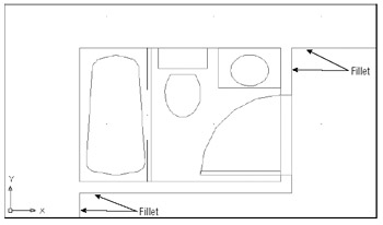
Figure 5.13: The cleaned-up wall intersections -
Fillet the top wall of the unit with the right-side wall of the bathroom, as shown in Figure 5.13.
Tip You can select two lines at once for the fillet operation by using a crossing window; type C
at the Select first object or prompt. The two endpoints closest to the fillet location are trimmed.
The location where you select the lines affects how the lines are joined. As you select objects for Fillet, the side of the line where you click is the side that remains when the lines are joined. Figure 5.14 illustrates how the Fillet command works and shows what the Fillet options do.
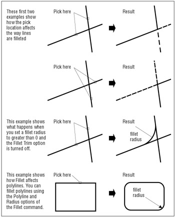
Figure 5.14: The place where you click the object to select it determines what part of an object gets filleted.
| Tip | If you select two parallel lines during the Fillet command, the two lines are joined with an arc. |
Now import the Kitchen plan you drew earlier in this chapter:
-
Click Insert Block on the Draw toolbar, and then browse to locate the kitchen drawing you created earlier in this chapter. Make sure you leave the Specify On-Screen check box unselected under the Scale and Rotation groups of the Insert dialog box.
-
Place the kitchen drawing at the wall intersection below the bathtub (see the top image in Figure 5.15).
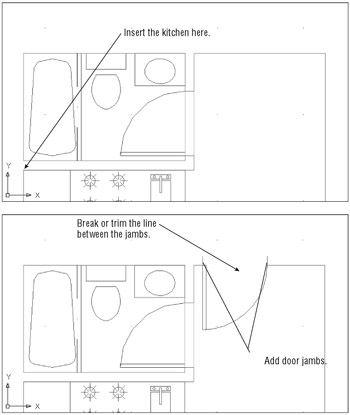
Figure 5.15: The view after using Pan, with the door inserted and the jamb and header addedTip If you didn't complete the kitchen earlier in this chapter, you can insert the 05a-kitchen.dwg file from the companion CD. Metric users can insert 05 kitchen-metric.dwg.
-
Adjust your view with Pan and Zoom so that the upper portion of the apartment unit is centered in the drawing area, as illustrated in the top image in Figure 5.15.
Placing the Door Accurately
The next step is to add the entry door shown in the bottom image in Figure 5.15. In doing that, you'll use a number of new tools together to streamline the drawing process.
In this exercise, you'll practice using the Osnap Tracking feature and the From Osnap option to place the entry door at an exact distance from the upper corner of the floor plan:
-
Right-click the Command window and choose Recent Commands Insert from the shortcut menu to open the Insert dialog box.
-
Select Door from the Name drop-down list.
-
Make sure the Specify On-Screen option is checked for the Rotation group but not in the Scale group , and then click OK. You'll see the door follow the cursor in the drawing window.
-
Shift+right-click the mouse to open the Osnap shortcut menu, and then choose From.
-
Make sure the Osnap and Otrack buttons on the status bar are on; then use the Endpoint Running Osnap to pick the corner where the upper horizontal wall line meets the bathroom wall.
-
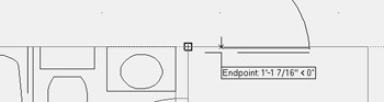
Move the cursor over the Osnap marker so that the Osnap Tracking vector appears from the corner. Now move the cursor to the right and you'll see the Osnap Tracking vector extend from the corner.
-
Continue to move the cursor to the right so that the tracking vector readout shows roughly 6 ² , or 15 cm for metric users.
-
With the cursor in this position, enter 5
. Metric users should enter 13 . The door is placed exactly 5 (or 13) units to the right of the corner. -
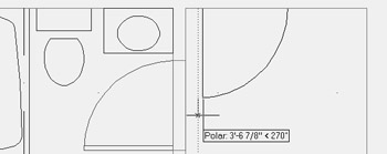
At the Specify rotation angle <0>: prompt, enter 270
. Or if you prefer, turn on Polar Tracking to orient the door so that it is swinging into the studio. You've now accurately placed the entry door in the studio apartment. -
Make sure the door is on the Door layer.
Tip For a shortcut to setting an object's layer, you can select the object or objects, and then select a layer from the Layer drop-down list in the Properties toolbar.
Now add the finishing touches to the entry door:
-
Add 5 ² (13 cm for metric users) door jambs and change their Layer property to the Jamb layer, as shown in the bottom image in Figure 5.15.
-
Choose the Break tool in the Modify toolbar, and then select the header over the entry door (see the bottom image in Figure 5.15).
-
Type F
to use the first-point option; then select the endpoint of one of the door jambs. -
At the Specify second break point: prompt, select the endpoint of the other jamb as shown in the bottom image in Figure 5.15.
-
Draw the door header on the Ceiling layer, as shown in Figure 5.16.
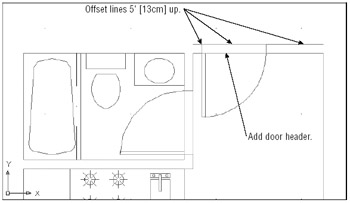
Figure 5.16: Offset lines 5" [13cm] up. -
Click Offset on the Modify toolbar, and offset the top wall lines of the unit and the door header up 5 ² (13 cm for metric users) so that they connect with the top end of the door jamb, as shown in Figure 5.16. Don't forget to include the short wall line from the door to the bathroom wall.
-
Choose File Save As to save your file as Unit .
| |
In the exercise for finishing the Unit plan, you used the Break command to accurately place a gap in a line over the entry door. In Chapter 4, you broke a line at a single point to create multiple, contiguous line segments.
In both cases you used the F option. You can also break a line without the F option with a little less accuracy. When you don't use the F option, the point at which you select the object is used as the first break point. If you're in a hurry, you can dispense with the F option and simply place a gap in an approximate location. You can then later use other tools to adjust the gap.
In addition, you can use locations on other objects to select the first and second points of a break. For example, you might want to align an opening with another opening some distance away. After you've selected the line to break, you can then use the F option and select two points on the existing opening to define the first and second break points. The break points will align in an orthogonal direction to the selected points.
| |
Using Polar and Osnap Tracking as Construction-Line Tools
So far, you've been using existing geometry to accurately place objects in the plan. In this section, you will use the Polar and Osnap Tracking toos to extend the upper wall line 5 ² (13 cm for metric users) beyond the right-side interior wall of the unit. You'll also learn how to use the Construction Line tool to accurately locate door jambs near the balcony.
Start by changing the Polar Tracking setting to include a 45 ° angle:
-
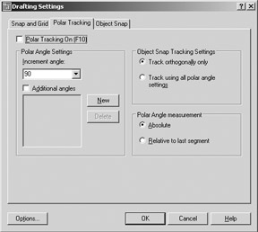
Right-click the Polar button in the status bar at the bottom of the AutoCAD window, and choose Settings to open the Drafting Settings dialog box at the Polar Tracking tab.
-
Select 45 from the Increment Angle drop-down list in the upper-left corner of the dialog box.
-
In the Object Snap Tracking Settings button group, make sure that the Track Using All Polar Angle Settings option is selected, and click OK.
You're ready to extend the wall line. For this operation, you'll use grip editing:
-
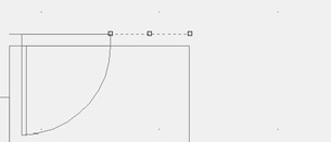
Click the wall line at the top of the plan, to the right of the door, to select the line and expose its grips.
-
Click the Ortho mode button to turn on Ortho mode in the status bar. This keeps the wall line straight as you edit it.
-
Click the rightmost grip of the line to make it "hot."
-
Place the cursor on the upper-right corner of the plan until you see the Endpoint Osnap marker; then move the cursor away from the corner at a 45 ° angle. The Osnap Tracking vector appears at a 45 ° angle. Notice the small X that appears at the intersection of the Osnap Tracking vector and the line.
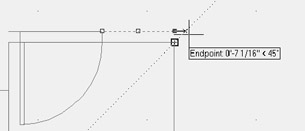
With the Osnap Tracking vector and the line intersecting, click the mouse button. The line changes to extend exactly 5 units beyond the vertical interior wall of the plan.
-
Press the Esc key twice to clear your selection. Then repeat steps 1 through 4 for the horizontal wall line to the left of the door, to extend that line to the left corner.
-
Choose View Zoom All to view the entire drawing. It will look like Figure 5.17.
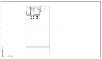
Figure 5.17: The studio unit so farTip With Polar Tracking set to 45 and Osnap Tracking turned on, you might find that you are selecting points that you don't really want to select in a crowded drawing. Just remember that if a drawing becomes too crowded, you can turn these options off temporarily by clicking the Otrack or Polar buttons in the status bar.
In this exercise, you used Polar Tracking and the Ortho mode to accurately position the two lines used for the exterior walls of the studio unit. This shows how you can take advantage of existing geometry with a combination of tools in the status bar.
| Tip | If you prefer to use a standard line instead of a construction line as a construction tool, you can use the ray (Draw Ray from the menubar). A ray is a line that starts from a point you select and continues off to an infinite distance. You specify the start point and angle of the ray. You can place a ray at the corner at a 45 ° angle and then fillet the ray to the horizontal wall line to shorten or lengthen the line to the appropriate length. |
Now you will finish the balcony by adding a sliding glass door and a rail. This time, you will use lines for construction as well as for parts of the drawing. First, you'll add the door jamb by drawing an Xline. An Xline is a line that has an infinite length, but unlike the ray, it extends in both directions. After drawing the Xline, you'll use it to quickly position the door jambs.
Follow these steps:
-
Zoom into the balcony area.
-
 Click the Construction Line tool from the Draw toolbar. You can also choose Draw Construction Line or type XL . You'll see this prompt:
 Specify a point or [Hor/Ver/Ang/Bisect/Offset]:
-
Type O
to select the Offset. -
At the Specify offset distance or [Through] <0 ¢ -5 ² >: prompt, type 4 ¢
. Metric users should type 122 . -
At the Select a line object: prompt, click the wall line at the right of the unit.
-
At the Specify side to offset: prompt, click a point to the left of the wall to display the Xline (see the top image of Figure 5.18).
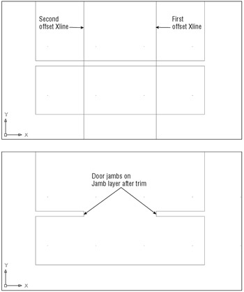
Figure 5.18: Drawing the door opening -
At the Select a line object: prompt, click the left wall line, and then click to the right of the selected wall to create another Xline. Your drawing should look like the top image in Figure 5.18.
Next, you'll edit the Xlines to form the jambs.
-
 Click Trim on the Modify toolbar.
 -
Select the Xlines and the two horizontal lines representing the wall between the unit and the balcony, and press
. You can either use a crossing window or select each line individually. You have just selected the objects to trim to. Tip You can also use the Fence selection option to select the lines to be trimmed. For more information, see Chapter 2 or Chapter 12.
-
Click the horizontal lines at any point between the two Xlines. Then click the Xlines above and below the horizontal lines to trim them. Your drawing will look like the bottom image in Figure 5.18.
-
Assign the the trimmed xlines to the Jamb layer.
-
Add lines on the Ceiling layer to represent the door header.
-
Now draw lines between the two jambs (on the Door layer) to indicate a sliding glass door (see Figure 5.19).
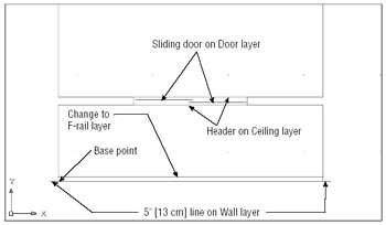
Figure 5.19: Finishing the sliding glass door
| |
There is more to the Xline command than you have seen in the exercises of this chapter. Here is a list of the Xline options and their uses:
Hor Draws horizontal Xlines as you click points.
Ver Draws vertical Xlines as you click points.
Angle Draws Xlines at a specified angle as you pick points.
Bisect Draws Xlines bisecting an angle or a location between two points.
Offset Draws Xlines offset at a specified distance.
| |
The wall facing the balcony is now complete. To finish the unit, you need to show a handrail and the corners of the balcony wall:
-
Offset the bottom line of the balcony 3 ² toward the top of the drawing. Metric users should offset the line 7.6 units.
-
Create a new layer called F-rail and assign this offset line to it.
-
Add a 5 ² (13 cm for metric users) horizontal line to the lower corners of the balcony, as shown in Figure 5.19.
-
Now choose Draw Block Base from the pull-down menu to set the base point at the lower-left corner of the balcony, at the location shown in Figure 5.19.
-
Assign the lines indicating walls to the Wall layer, and put the sliding glass door on the Door layer (see Figure 5.19).
-
Zoom back to the previous view. Your drawing should now look like Figure 5.20.
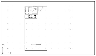
Figure 5.20: The completed studio apartment unit -
Choose File Save to save the drawing.
Your studio apartment unit plan is now complete. The exercises you've just completed demonstrate a typical set of operations you'll perform while building your drawings. In fact, nearly 80 percent of what you will do in AutoCAD is represented here.
Now, to review the drawing process, and to create a drawing you'll use later, you're going to draw the apartment building's lobby. As you follow the steps, refer to Figure 5.21.
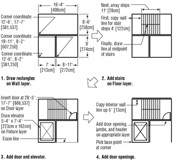
Figure 5.21: Drawing the lobby plan. Metric dimensions are shown in brackets.
On the CD As is usual in floor plans, the elevator is indicated by the box with the large X through it, and the stair shaft is indicated by the box with the row of vertical lines through it. If you are in a hurry, use the finished version of this file on the companion CD called Lobby.dwg ( Lobby-metric.dwg for metric users).
To draw the apartment building lobby, follow these steps:
-
Create a new file called Lobby , using the Unit file as a prototype. (Open the Unit file, choose File Save As, and enter Lobby for the new filename.)
-
Erase the entire unit (choose Erase All).
-
Begin by drawing the three main rectangles that represent the outlines of the stair shaft, the elevator shaft, and the lobby.
-
To draw the stairs, offset the stair shaft's left wall to the right a distance of 4 ¢ (122 cm). This creates the first line representing the steps.
-
Array this line in one row of 10 columns , using 11 ² (28 cm) column spacing.
-
Draw the center line dividing the two flights of stairs.
-
Draw the elevator and insert the door. Practice using Xlines here.
-
Draw the door jambs. Edit the door openings to add the door headers. Your plan should resemble the one in Figure 5.21, step 4.
-
Save the Lobby file.
Finding Distances Along Arcs
You've seen how you can use lines to help locate objects and geometry in your drawing. But if you need to find distances along a curved object such as an arc, lines don't always help. This section describes two ways to find exact distances on arcs. Try these exercises when you're not working through the main tutorial.
Finding a Point at a Particular Distance from Another Point
At times you'll need to find the location of a point on an arc that lies at a known straight-line distance from another point on the arc. The distance can be described as a chord of the arc, but how do you find the exact chord location? To find a chord along an arc, follow these steps.
-
Click the Circle tool on the Draw toolbar or type C
. -
Use the Endpoint Osnap to click the endpoint of an arc.
-
At the Specify radius of circle or [Diameter]: prompt, enter the length of the chord distance you want to locate along the arc.
The point where the circle intersects the arc is the endpoint of the chord (see Figure 5.22). You can then use the Intersect Osnap override to select the circle and arc intersection.
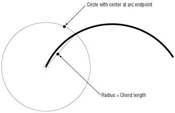
Figure 5.22: Circle with center at arc endpoint
| |
As your list of layers grows, you might find it difficult to locate the exact layer you want quickly. You might know that you want to draw objects on the same layer as an existing object in a drawing, but maybe you are not sure what that layer is.
![]() AutoCAD offers the Make Object's Layer Current tool to help you easily set the current layer. This tool can be found on the Properties toolbar next to the Layers tool.
AutoCAD offers the Make Object's Layer Current tool to help you easily set the current layer. This tool can be found on the Properties toolbar next to the Layers tool.
This simple yet powerful tool lets you set the current layer by selecting an object in the drawing instead of selecting its name from a list. To use it, click the Make Object's Layer Current tool, and then click the object whose layer you want to make current. This reduces the three-step or four-step process of earlier AutoCAD versions to one click.
Remember this tool the next time you are faced with a drawing that has a long list of layers.
| |
Finding an Exact Distance Along an Arc
To find an exact distance along an arc or curve (nonlinear), or to mark off specific distance increments along an arc or curve, do the following:
-
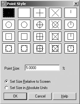
Choose Format Point Style from the pull-down menu to open the Point Style dialog box.
-
In the Point Style dialog box, click the X icon in the top row. Also be sure the Set Size Relative To Screen radio button is selected. Then click OK.
Tip You can also set the point style by setting the Pdmode system variable to 3. See Appendix D for more on Pdmode.
-
Choose Draw Point Measure from the pull-down menu or type me
. Tip The Divide command (choose Draw Point Divide) marks off a line, an arc, or a curve into equal divisions, as opposed to divisions of a length you specify. You might use Divide to divide an object into 12 equal segments, for example. Aside from this difference in function, Divide works in exactly the same way as Measure.
-
At the Select object to measure: prompt, click the end of the arc that you want to use as the starting point for your distance measurement.
-
At the Specify length of segment or [Block]: prompt, enter the distance you want. A series of Xs appears on the arc, marking off the specified distance along the arc. You can select the exact location of the Xs by using the Node Osnap override (see Figure 5.23).
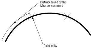
Figure 5.23: Finding an exact distance along an arc by using points and the Measure commandTip The Block option of the Measure command enables you to specify a block to be inserted at the specified segment length, in place of the Xs on the arc. You can align the block with the arc as it is inserted. (This is similar to the polar array's Rotate Objects As They Are Copied option.)
The Measure command also works on Bezier curves. You'll get a more detailed look at the Measure command in Chapter 13.
As you work with AutoCAD, you'll find that constructing temporary geometry such as the circle and points in the two previous examples will help you solve problems in new ways. Don't hesitate to experiment! Remember, you've always got the Save and Undo commands to help you recover from mistakes.
Changing the Length of Objects
Suppose that, after finding the length of an arc, you realize you need to lengthen the arc by a specific amount. Choosing Modify Lengthen lets you lengthen or shorten arcs, lines, splines, and elliptical arcs. As an example, here's how to lengthen an arc:
-
Choose Modify Lengthen or type len
. -
At the Select an object or [DElta/Percent/Total/DYnamic]: prompt, type T
. -
At the Specify total length or [Angle] <1.0000)>: prompt, enter the length you want for the arc.
-
At the Select an object to change or [Undo]: prompt, click the arc you want to change. Be sure to click at a point nearest the end you want to lengthen. The arc increases in length to the size you specified.
The Lengthen command also shortens an object if it is currently longer than the value you enter. In this short example, you have learned how to change an object to a specific length. You can use other criteria to change an object's length, using these options available for the Lengthen command:
DElta Lets you lengthen or shorten an object by a specific length. To specify an angle rather than a length, use the Angle suboption.
Percent Lets you increase or decrease the length of an object by a percentage of its current length.
Total Lets you specify the total length or angle of an object.
DYnamic Lets you graphically change the length of an object by using your cursor.
Creating a New Drawing by Using Parts from Another Drawing
This section explains how to use the Wblock command (which you learned about in Chapter 4) to create a separate staircase drawing by using the staircase you've already drawn for the lobby. Although you haven't turned the existing stairs into a block, you can still use Wblock to turn parts of a drawing into a file.
Follow these steps:
-
On the CD If you closed the Lobby file, open it now. If you didn't create the lobby drawing, open the Lobby.dwg (or Lobby-metric.dwg ) file from the companion CD.
-
Chose File Export or type export
to open the Export Data File dialog box. -
Enter stair.dwg in the File Name text box and click Save. By including the .dwg filename extension, you let AutoCAD know that you want to export to a drawing file and not some other format, such as a .dxf or .wmf file format.
-
At the Enter name of existing block or [= (block=output file)/* (whole drawing)] <define new drawing>: prompt, press
. When you export to a .dwg format, AutoCAD assumes you want to export a block. Bypassing this prompt by pressing tells AutoCAD that you want to create a file from part of the drawing, rather than from a block. -
At the Specify insertion base point: prompt, pick the lower-right corner of the stair shaft. This tells AutoCAD the base point for the new drawing.
-
At the Select objects: prompt, use a window to select the stair shaft, as shown in Figure 5.24.
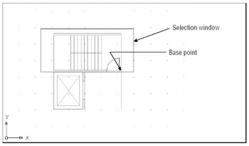
Figure 5.24: A selection window enclosing the stair shaft -
When the stair shaft, including the door, is highlighted, press
to confirm your selection. The stairs disappear. -
Because you want the stairs to remain in the lobby drawing, click the Undo button to bring them back. Undo does not affect any files you might export by choosing File Export, by using Wblock, or by using the Make Block tool.
EAN: 2147483647
Pages: 261