Copying an Object Multiple Times
Now let's explore the tools that let you quickly duplicate objects. In this section, you will begin to draw parts of a small kitchen. The first exercise introduces the Array command, which you can use to draw the gas burners of a range top.
As you'll see, an array can be in either a circular pattern, called a polar array, or a matrix of columns and rows, called a rectangular array.
Making Circular Copies
To start the range top, first set the layer on which you want to draw, and then draw a circle representing the edge of one burner :
-
Set the current layer to Fixture, and turn on the Grid Snap mode by right-clicking the Snap button in the status bar and selecting Grid Snap On.
Tip Because you used the Bath file as a template, Running Osnaps for Endpoint, Midpoint, and Intersection are already turned on and available in this new file.
-
 Click the Circle tool on the Draw toolbar or type C
  .
. -
At the Specify Center point for circle or [3P/2P/Ttr (tan tan radius)]: prompt, pick a point at coordinate 4 ¢ ,4 ¢ . Metric users should pick a point at coordinate 120,120.
-
At the Specify radius of circle or [Diameter]: prompt, enter 3
. Metric users should enter 7.6 . The circle appears.
Now you're ready to use the Array command to draw the burner grill. You will first draw one line representing part of the grill and then use the Array command to create the copies:
-
Turn off both the Polar Snap and Grid Snap modes by clicking the Snap button in the status bar, and draw a 4 ² line starting from the coordinate 4 ¢ -1 ² , 4 ¢ -0 ² and ending to the right of that point. Metric users should draw a 9 cm line starting at coordinate 122,120 and ending to the right of that point.
-
Zoom into the circle and line to get a better view. Your drawing should look like Figure 5.1.
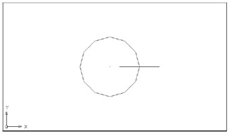
Figure 5.1: A close-up of the circle and line
You've got the basic parts needed to create the burner grill. Now you're ready to make multiple copies of the line. For this part, you'll use the Array dialog box:
-
 Click Array on the Modify toolbar or type AR . The Array dialog box appears.
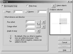
-
Click the Select Objects button. The dialog box temporarily disappears, enabling you to select objects.
-
Type L
to select the last object drawn, or click the object you want to array. -
Press
to confirm your selection. The Array dialog reappears. -
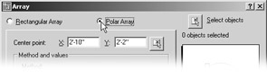
Click the Polar Array radio button at the top of the dialog box to tell AutoCAD you want a circular array. The Array dialog box displays the Polar Array options.
-
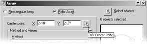
Click the Pick Center Point button to temporarily close the Array dialog box.
-
Pick the point that represents the center of the circular array. Use Center Osnap to select the center of the circle. After you've indicated a point, the Array dialog box returns.
Tip Remember that to access Osnaps other than those set up as Running Osnaps, you Shift+right-click the mouse and then select the Osnap you want to use from the resulting menu.
Warning If you use Center Osnap, you must place the cursor on the circle's circumference, not on the circle's center point.
At this point, you've selected an object to array, and you've indicated the center location of the array. If you've selected the wrong object or the wrong center point, you can go back and specify these options again.
Now, to complete the process, tell AutoCAD the number of copies in the array and the extent of the array through the circle:
-
In the Array dialog box, enter 8 in the Total Number Of Items text box. This tells AutoCAD to make eight copies including the original.
-
Accept the default of 360 for the Angle To Fill text box. This tells AutoCAD to spread the copies evenly over the full 360 degrees of the circle. Of course, you can enter other values here. For example, if you enter 180, the array will fill half the circle.
Tip You can click the Pick Angle To Fill button to the right of the Angle To Fill box to graphically select an angle in the drawing.
-
Make sure the Rotate Items As Copied check box in the lower-left corner of the dialog box is selected. This ensures that the arrayed object is rotated about the array center. If you clear this option, the copies will all be oriented in the same direction as the original object.
-
Click the Preview button. AutoCAD shows you the results of your array settings plus a dialog that offers Accept, Modify, and Cancel.
-
Click Accept. The circular array appears in the drawing, as shown in Figure 5.2.
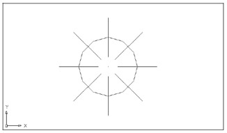
Figure 5.2: The completed gas burner
In step 5, you could have selected the Modify option to return to the Array dialog box and change settings before committing to a final array pattern, or you could click Cancel to cancel the whole process. The Array dialog box gives you a lot of leeway in creating your array copies.
| Tip | If you're a veteran AutoCAD user and you prefer the command-line version of the Array command, you can type “Array |
Making Row and Column Copies
Now you will draw the other three burners of the gas range by creating a rectangular array from the burner you just drew. You will first zoom back a bit to get a view of a larger area. Then you will proceed with the Array command.
Follow these steps to zoom back:
-
Choose View Zoom Scale, or type Z
S . -
Enter .5x
. Your drawing will look like Figure 5.3. 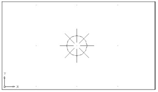
Figure 5.3: The preceding view reduced by a factor of 0.5Tip If you're not too fussy about the amount you want to zoom out, you can choose View Zoom Out to quickly reduce your view, or you can click the Zoom Realtime tool on the Standard toolbar.
Entering .5x for the Zoom Scale value tells AutoCAD you want a view that reduces the width of the current view to fill half the display area, enabling you to see more of the work area. If you specify a scale value greater than 1 (5, for example), you will magnify your current view. If you leave off the x , your new view will be in relation to the drawing limits rather than the current view.
Now you will finish the range top. Here you will get a chance to use the Rectangular Array option to create three additional burners:
- Click the Array tool on the Modify toolbar again or type AR to open the Array dialog box.
-
Click the Select Objects tool to temporarily close the Array dialog box.
-
Select the entire burner, including the lines and the circle, and then press
to confirm your selection. -
In the Array dialog box, click the Rectangular Array radio button.
-
Change both the Rows and Columns text boxes to 2 .
-
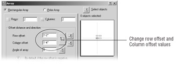
Change the Row Offset text box value to 1 ¢ - 2 ² (35.5 for metric users) and the Column Offset text box value to 1 ¢ - 4 ² (or 40.6 for metric users).
-
Click OK. Your screen will look like Figure 5.4.
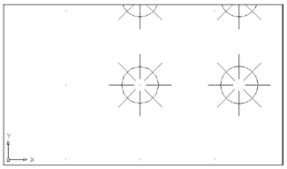
Figure 5.4: The burners arrayed
AutoCAD usually draws a rectangular array from bottom to top and from left to right. You can reverse the direction of the array by giving negative values for the distance between columns and rows.
| Tip | At times, you might want to create a rectangular array at an angle. To accomplish this, enter the desired angle in the Angle Of Array text box of the Array dialog box. You can also select the angle graphically by clicking the Pick Angle Of Array button just to the right of the Angle Of Array text box. |
If you need to graphically indicate an array cell , you can do so by using options in the Offset Distance And Direction group of the Array dialog box (see the bottom image in Figure 5.5). An array cell is a rectangle defining the distance between rows and columns (see the top image in Figure 5.5).
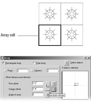
Figure 5.5: An array cell and the Array dialog box options that let you graphically indicate array cells
You might want to use this option when objects are available to use as references from which to determine column and row distances. For example, you might have drawn a crosshatch pattern, as on a calendar, within which you want to array an object. You use the intersections of the hatch lines as references to define the array cell, which is one square in the hatch pattern.
In the Offset Distance And Direction group, the Pick Both Offsets button lets you indicate the row and column distance by placing an array cell graphically in the drawing, as shown in the bottom image in Figure 5.5. You can also indicate a row or column distance graphically by using the Pick Row Offset or Pick Column Offset buttons to the right of the Pick Both Offsets button.
Fine-Tuning Your View
To activate the Pan command, follow these steps:
-
 Click the Pan Realtime tool on the Standard toolbar, choose View Pan Realtime, or type P . You can also right-click and choose Pan from the shortcut menu. A small hand-shaped cursor appears in place of the AutoCAD cursor.
-
Place the hand cursor in the center of the drawing area, and then click and drag it downward and to the left. The view follows the motion of your mouse.
-
Continue to drag the view until it looks similar to Figure 5.6; then release the mouse button.
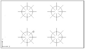
Figure 5.6: The panned view of the range top -
To finish the kitchen, you will want a view that shows more of the drawing area. Right-click to open the Zoom/Pan shortcut menu, then choose Zoom. The cursor changes to the Zoom Realtime cursor. The Zoom/Pan shortcut menu also appears when you right-click during the Zoom Realtime command.
-
Place the cursor close to the top of the screen, and click and drag the cursor downward to zoom out until your view looks like the top panel of Figure 5.7. You might need to click and drag the Zoom Realtime cursor a second time to achieve this view.
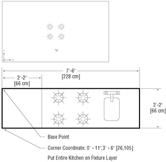
Figure 5.7: The final view of the range top burners (top image) and the finished kitchen (bottom image). Metric dimensions are shown in brackets. -
Right-click the mouse again, and choose Exit from the shortcut menu. You're now ready to add more information to the kitchen drawing.
Tip To exit the Pan Realtime or Zoom Realtime command without opening the shortcut menu, press the Esc key.
This exercise showed how you can fine-tune your view by easily switching between Pan Realtime and Zoom Realtime. After you get the hang of these two tools working together, you'll be able to quickly access the best view for your needs. The other options in the shortcut menu ”Zoom Window, Zoom Original, and Zoom Extents ”perform the same functions as the options in the View pull- down menu.
| Tip | The Zoom Window option in the Zoom shortcut menu functions in a slightly different way from the standard Zoom Window option. Instead of clicking two points, you click and drag a window across your view. |
While we're on the subject of display tools, don't forget the scroll bars to the right and bottom of the AutoCAD drawing area. They work like any other Windows scroll bars, offering a simple way to move up, down, left, or right in your current view. They also come in handy for quickly panning your view in one direction or another.
If for some reason the scroll bars do not appear in AutoCAD, or if you prefer to turn them off, open the Options dialog box (choose Tools Options), click the Display tab, and make sure that Display Scroll Bars in the Drawing Window option is either selected to turn them on or cleared to turn them off.
Finishing Up the Kitchenette
Before you save and close the Kitchen file, you need to do one more thing. You will be using this drawing as a symbol and inserting it into the overall plan of the studio apartment unit. To facilitate accurate placement of the kitchen, you will want to change the location of the base point of this drawing to the upper-left corner of the kitchen. This will then be the grip of the drawing.
-
Complete the kitchenette as indicated in the bottom panel of Figure 5.7. As the figure indicates, make sure you put the kitchenette on the Fixture layer. This will help you control the visibility of the kitchenette in future edits of this file.
-
Choose Draw Block Base from the pull-down menu.
-
At the Enter base point: prompt, pick the upper-left corner of the kitchen, as indicated in the bottom image of Figure 5.7. The kitchen drawing is complete.
-
Choose File Save.
| |
Choosing Draw Array is useful when you want to make multiple copies in a regular pattern. But what if you need to make copies in a random pattern? You can do this in two ways: by using the Copy command's Multiple option and by using the Grips Move option.
If you've used AutoCAD before, you'll notice that the Copy command in AutoCAD 2005 has changed slightly. To use the Copy command to make random multiple copies, follow these steps:
-
Click Copy Objects on the Modify toolbar or type CO
. -
At the Select objects: prompt, select the objects you want to copy and press
to confirm your selections. -
At the Specify base point or displacement: prompt, enter M
to select the Multiple option. -
At the Specify base point: prompt, select a base point as usual.
-
At the Specify second point or displacement or <use first point as displacement>: prompt, select a point for the copy. You will be prompted again for a second point, enabling you to make yet another copy of your object.
-
Continue to select points for more copies as desired.
-
Press
to exit the Copy command.
When you use the Grips feature to make multiple random copies, you get an added level of functionality because you can also rotate, mirror, and stretch copies by using the shortcut menu (right-click while a grip is selected). Of course, you must have the Grips feature turned on; it is usually on by default, but you might find yourself on a system that has it turned off for some reason.
Follow these steps to use the Grips Move option for making random multiple copies:
-
Press the Esc key to make sure you are not in the middle of a command; then select the objects you want to copy.
-
Click a grip point as your base point.
-
Right-click your mouse and select Move.
-
Right-click again and select Copy.
-
Click the location for the copy. Notice that the rubber-banding line persists and that you still see the selected objects follow the cursor.
-
If desired, click other locations for more copies.
Finally, you can use grips to make square-arrayed copies by following steps 1 through 3, but instead of step 4, Shift+click a copy location. Continue to hold down the Shift key and select points. The copies snap to the angle and distance you indicate with the first Shift+select point. Release the Shift key to make multiple random copies.
| |
EAN: 2147483647
Pages: 261