You've covered a lot of territory in this chapter, so it might be a good idea to play with these commands to help you remember what you've learned. Try the exercise shown in Figure 16.50.
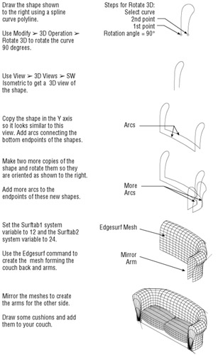
Figure 16.50:
Drawing a 3D over- stuffed
ACAD only
Just a few
In this chapter, you'll learn how to use rendering tools in AutoCAD to produce rendered still images of your 3D models. With these tools, you can add materials, control lighting, and even add landscaping and people to your models. You also have control over the reflectance and transparency of objects, and you can add bitmap backgrounds to help set the mood.
| Warning |
AutoCAD 2005 LT does not support any of the features described in this chapter. |
You will want to take certain steps before you start working with the rendering tools so you won't run into problems later. First, make sure you have your virtual memory set to a decent size. Setting your virtual memory
Throughout this chapter, you will work with a 3D model that was created using AutoCAD's solid modeling tools. (You'll learn more about solid modeling in Chapter 18.) The model is of two
On the CD
Open the Render toolbar from the Toolbar dialog box.
Choose View
Render
Render or click the Render tool in the Render toolbar to open the Render dialog box. In time, you will become intimately familiar with this dialog box.
Click the Render button. AutoCAD takes a second or two to render the current view. While it's working, you will see messages in the Command window showing you the progress of the rendering. When AutoCAD is finished, the surface-shaded model appears (see Figure 17.1).
Figure 17.1:
The Facade model rendered using all the default settings
When you render a model without any special settings, you create what is called a
Z buffer shaded model.
(A
Z buffer
is like a work area in memory, where the distance between surfaces along a view's z-axis can be compared. This helps AutoCAD determine which surfaces overlap.) The surfaces are shaded in their color, and the light source is, by default, from the camera location. This view is much like a hidden-line view with
The ability to add a sunlight source to a drawing is one of AutoCAD's key features. The Sun Angle Calculator tool is used frequently in the design of buildings in urban and suburban settings. Neighboring building
So let's add the sun to our model to give a better sense of the building's form and relationship to its site:
Choose View
Render
Light or click Lights on the Render toolbar to open the Lights dialog box.
| Tip |
Whenever you are creating a new light or other object with the Render dialog boxes, you usually have to give it a
|
Choose Distant Light from the drop-down list
Click the New button to open the New Distant Light dialog box. This dialog box lets you control various aspects of the light source, such as color and location.
Type Sun in the Light Name input box.
Because you want to simulate the sun in this example, click the Sun Angle Calculator button to open the Sun Angle Calculator dialog box. Notice that you have options for setting the date and time to determine the exact location of the sun. In addition, you can
One important factor for calculating the sun angle is finding your location on the earth. Click the Geographic Location button to open the Geographic Location dialog box. Here you can tell AutoCAD where your building is located in the world.
For the sake of this tutorial, suppose the Facade model is a building in San Francisco, California, USA. Select North America from the drop-down list above the map.
Locate and select San Francisco CA in the scrolling list to the left of the map. Notice that the Latitude and Longitude input boxes below the list change to reflect the location of San Francisco. For locations not listed, you can enter values manually in those input boxes.
Now click OK to return to the Sun Angle Calculator dialog box. Set the date for
9
/
21
and the time for 14:00 hours. Notice that the graphic to the right of the dialog box
Click OK in the Sun Angle Calculator dialog box, click OK in the New Distant Light dialog box, and then click OK again in the Lights dialog box.
Choose View Render Render or click Render on the Render toolbar. Then click the Render button in the Render dialog box. Your model will be shaded to reflect the sun's location (see Figure 17.2).
Figure 17.2:
The Facade model with the sun light source added
Notice that the building itself looks darker than before and that the ground plane is lighter. Remember that in the first rendering, the light source was the same as the camera location, so the wall
If you are including the sun as a light source in a drawing in order to run shade studies, it's essential to
Figure 17.3:
The North Location dialog box
By using this dialog box, you can set true north in any of the following ways:
Click the graphic to point to the direction.
Use the slide bar at the bottom to move the arrow of the graphic and adjust the value in the input box.
Enter a value directly in the input box.
You can also indicate which UCS is used to set the north direction. For example, you might have already set a UCS to point to the true north direction. You only need to select UCS from the list and leave the angle at 0.
|
|
You might notice that at times when using the Render, Hide, or Shade tool, solid or region arcs appear segmented rather than
You can modify the Rendered Object Smoothness setting in the Display tab of the Options dialog box to improve the smoothness of arcs. Its default setting is 0.5, but you can increase this to as high as 10 to smooth out
|
|
There is nothing like adding shadows to a 3D rendering to give the model a sense of
In the following exercise, you will use the Shadow Map method. It requires the most adjustments and yields a faster rendering. Here are the steps:
Choose View Render Lights or click Lights on the Render toolbar to open the Lights dialog box.
Make sure Sun is highlighted, and then click Modify to open the Modify Distant Light dialog box.
| Tip |
When adding shadows, remember that you must
|
Click the Shadow On check box to select it, and then click the Shadow Options button to open the Shadow Options dialog box.
In the Shadow Map
Click the Shadow Bounding Objects button. The dialog box temporarily
Select the entire Facade building. Don't select any of the building next to it. When you are finished, press
. The Shadow Options dialog box reappears.
Click OK to close the Shadow Options dialog box, and then click OK in the Modify Distant Light dialog box. It might take several seconds before the dialog box closes.
When you get to the Lights dialog box, click OK to close it.
Click the Render button on the Render toolbar.
In the Render dialog box, click the Shadows check box to select it and then click the Render button. After a minute or two, the model appears rendered with shadows (see Figure 17.4).
Figure 17.4:
The Facade model rendered with shadows by using the Shadow Map method
Don't panic if the shadows don't appear correct. The Shadow Map method needs some adjustment before it will give the proper shadows. The default settings are appropriate for views of objects from a greater distance than our current view. The following exercise will show you what to do for close-up views:
Open the Render dialog box again, and then click the More Options button to open the Photo Real Render Options dialog box.
In the Depth Map Shadow Controls
In the same group, change the Maximum Bias value from 4 to 0.2.
Click OK to close the Photo Real Render Options dialog box and then click Render. Your next rendering will show more accurately drawn shadows (see Figure 17.5).
Figure 17.5:
The rendered view with the Shadow Bias settings revised
The shadow still looks a bit rough. You can further refine its appearance by increasing Shadow Map Size to greater than 512. This setting can be found in the Shadow Options dialog box in step 4 of the exercise in the "Adding Shadows" section. As you increase the map size, you also increase render time and the amount of RAM required to render the view. If you don't have enough free disk space, Auto- CAD might
Notice that the shadow has a soft edge. You can control the softness of the shadow edge by using the Shadow Options dialog box. The Shadow Softness input box and slide bar let you sharpen the shadow edge by
The rendering methods you've learned so far can be of
Let's suppose you want a granite-like finish to appear on the Facade model. You also want the building next to the Facade model to appear as a glass tower. The first step in adding materials is to acquire the materials from AutoCAD's materials library:
Choose View
Render
Materials or click Materials on the Render toolbar to open the Materials dialog box.
Click the Materials Library button to open the Materials Library dialog box.
In the Current Library list box, find and select Granite Pebbles. This is the material you will assign to the facade.
Click the Preview button in the middle of the dialog box to display a view of the material on a sphere, giving you an idea of what the material looks like.
Click the Import button. Notice that Granite Pebbles now appears in the list box in the Current Drawing group to the left. This list box shows the materials you've transferred to your drawing.
Now locate Glass in the list on the right and select it. Click the Preview button again to see what it looks like. Notice that the preview displays a transparent sphere showing some reflected light. You might notice a textured effect caused by the low color resolution of the AutoCAD display.
Click the Import button again to make Glass available in the drawing; then click OK to exit the Materials Library dialog box.
After you've
In the Materials dialog box, highlight the Granite Pebbles item shown in the list on the left, and then click the Attach button on the right side of the dialog box. The dialog box temporarily disappears, enabling you to select the objects you want to appear as granite.
Click the Facade model, including the steps,
. After a moment, the Materials dialog box appears again.
Click Glass in the Materials list.
This time you'll assign a material based on its layer. Click the By Layer button on the right side of the dialog box to open the Attach By Layer dialog box.
Shift+click Glass and Dkglass from the Select Layer list to the right, and then click the Attach button. Notice that the word
Glass
now appears next to the layer
Click OK to exit the Attach By Layer dialog box; then click OK again to exit the Materials dialog box.
Now render your model. When AutoCAD is finished, your rendering will look like Figure 17.6.
Figure 17.6:
The Facade model with the glass and granite pebbles materials added
At this point, the Facade model looks like it has an army camouflage paint job instead of a granite finish. Also, the glass of the office tower is a bit too transparent. Fortunately, you can make several adjustments to the materials. You will want to reduce the scale of the granite pebbles material so it is in line with the scale of the model. You will also want to
You'll start with the granite pebbles:
Choose View Render Materials or click the Materials tool on the Render toolbar to open the Materials dialog box.
Select Granite Pebbles from the Materials list, and then click the Modify button to open the Modify Granite Material dialog box.
Click the Scale radio button in the Attributes group of the dialog box.
Change the Value input box near the top of the dialog box from 0.398 to 0.010. This
Click OK to return to the Materials dialog box.
The Modify Granite Material dialog box offers a variety of options that let you control reflectivity, roughness, color, transparency, and, of course, scale. Click the Help button to display a brief description of these options. As you'll see when you continue with the next exercise, not all materials have the same options:
Select Glass from the Materials list, and then click the Modify button again to open the Modify Standard Material dialog box. Notice that this dialog box offers a slightly different set of attributes than those in the Modify Granite Material dialog box you edited in the previous exercise.
Click the Transparency radio button in the Attributes group and then adjust the Value option downward to 0.55. This has the effect of darkening the glass.
Click the Color/Pattern radio button; then, in the Color group, adjust the Red value to 0.69, the Green value to 0.60, and the Blue to 0.58. This gives the glass a bronze tint.
Select Cube from the drop-down list just below the Preview button, and then click the Preview button to get a preview of the color settings.
Click OK in both the Modify Standard Material and Materials dialog boxes to exit them.
Render the view with the new material settings. After a few seconds, your view will look something like Figure 17.7.
Figure 17.7:
The Facade model after modifying the material settings
There are four basic types of materials: Standard, Marble, Granite, and Wood. Each type has its own set of characteristics that you can adjust. You can even create new materials based on one of the four primary types of materials. Now let's continue by making another adjustment to the material settings.
The granite surface of the Facade is still a bit too strong. You can reduce the graininess of the granite by further editing in the Modify Granite Material dialog box:
Click the Materials tool on the Render toolbar to open the Materials dialog box. Select Granite Pebbles from the Materials list, and then choose Modify to open the Modify Granite Material dialog box.
Click the Sharpness radio button. Then set the Value input box to 0.20.
Click OK, and then click OK again in the Materials dialog box.
Choose View Render Render to open the Render dialog box, and then click the Render button. Your rendering appears after a few seconds with a finer granite surface (see Figure 17.8).
Figure 17.8:
The rendered image with a finer granite surface