Chapter 16: Using Advanced 3D Features
AutoCAD's extended set of tools for working with 3D drawings lets you create 3D objects with few limitations on shape and orientation. This chapter focuses on the use of these tools, which help you easily generate 3D forms and view them in both the Perspective and Orthogonal modes.
Mastering the User Coordinate System
The User Coordinate System (UCS) enables you to define a custom coordinate system in 2D and 3D space. In fact, you've been using a default UCS, called the World Coordinate System (WCS) , all along. By now you are familiar with the L-shaped icon in the lower-left corner of the AutoCAD screen, containing a small square and the letters X and Y. The square indicates that you are currently in the WCS; the X and Y indicate the positive directions of the x- and y-axes. WCS is a global system of reference from which you can define other User Coordinate Systems.
It might help to think of these AutoCAD User Coordinate Systems as different drawing surfaces, or two-dimensional planes. You can have several User Coordinate Systems at any given time. By setting up these different UCSs, you can draw as you would in the WCS in 2D, yet draw a 3D image.
Suppose you want to draw a house in 3D with doors and windows on each of its sides. You can set up a UCS for each of the sides; then you can move from UCS to UCS to add your doors and windows (see Figure 16.1). Within each UCS, you draw your doors and windows as you would in a typical 2D drawing. You can even insert elevation views of doors and windows that you created in other drawings.
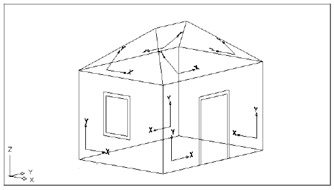
Figure 16.1: Different User Coordinate Systems in a 3D drawing
In this chapter, you will be experimenting with several views and UCSs. All the commands you will use are available both at the command line and via the menu bar. In addition, you can access a number of the UCS commands from the UCS toolbar.
Defining a UCS
In the first set of exercises, you will draw a chair that you can later add to your 3D unit drawing. In drawing this chair , you will be exposed to the use of the UCS, as well as to some of the other 3D capabilities available in AutoCAD.
Begin the chair by drawing the seat and seat back:
-
Start AutoCAD and create a new file called Barcelon .
-
Set up your drawing as an architectural drawing with a scale of 1 ² = 1 ¢ -0 ² on an 8 ½ ² 11 ² sheet. Set the upper-right corner of the limits to 132 102. If you're a metric user, you'll be drawing the chair at a scale of 1:10 on an A4 sheet. Your work area should be 297 210, which is the equivalent of a 297 cm 210 cm area.
Tip If you are a metric user and you prefer to work in millimeters, you can set the upper-right corner of the limits to 2970,2100. Then, when the book specifies a length or coordinate, multiply the specified value by 10. For example, 50 cm becomes 500 mm. Coordinate 50,50 becomes 500,500. Your scale factor would also change to 100.
-
Choose View Zoom All or type Z
 A .
A . -
 To draw the seat of the chair, click the Rectangle tool on the Draw toolbar. Draw a rectangle measuring 20 ² in the x-axis and 30 ² in the y-axis. Position the rectangle so the lower-left corner is at the coordinate 2 ¢ -0 ² ,2 ¢ -0 ² (see the top image in Figure 16.2). Metric users should draw a rectangle that is 50 cm by 76 cm with its lower-left corner at coordinate 50,50.
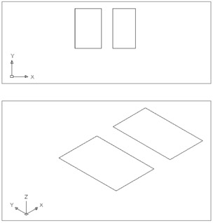
Figure 16.2: The chair seat and back in the Plan (top) and Isometric (bottom) views -
To draw the back of the chair, draw another rectangle 17 ² in the x - axis and 30 ² in the y-axis, just to the right of the previous rectangle (see the top image in Figure 16.2). Metric users should make this rectangle 43 cm 76 cm.
-
Choose View 3D Views SW Isometric. This gives you a 3D view from the lower-left of the rectangles, as shown in the bottom image in Figure 16.2.
-
Select the two rectangles, and then click the Properties tool on the Standard toolbar.
-
In the Properties palette, enter 3 in the Thickness setting and click OK. This gives the seat and back a thickness of 3 ² . Metric users should make the thickness 7.6 cm.
-
Close the Properties palette.
-
Zoom out a bit and give yourself some room to work.
Notice that the UCS icon appears in the same plane as the current coordinate system. The icon will help you keep track of which coordinate system you are in. Now you can see the chair components as 3D objects.
Next , you will define a UCS that is aligned with one side of the seat:
-
Right-click any toolbar and choose UCS from the shortcut menu to open the UCS toolbar.
-
 Click the Display UCS Dialog tool in the UCS toolbar to open the UCS dialog box. You could also choose Tools Named UCS from the toolbar.
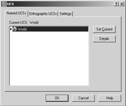
-
Select the Orthographic UCSs tab to view a set of predefined UCSs.
-
Select Front in the list box. Figure 16.3 shows the orientation of the Front UCS.
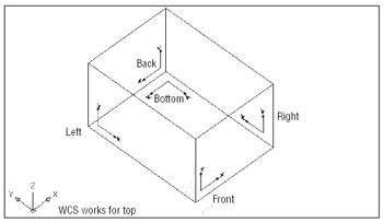
Figure 16.3: The six predefined UCS orientations -
Click the Set Current button to make the Front UCS current.
-
Click OK to close the dialog box.
The Orthographic UCSs tab offers a set of predefined UCSs for each of the six standard ortho - graphic projection planes. Figure 16.3 shows these UCSs in relation to the World Coordinate System. You can also access these orthographic UCSs from the Tools Orthographic UCS cascading menu or from the UCS dialog box.
Because a good part of 3D work involves drawing in these orthographic planes, AutoCAD supplies these ready-made UCS orientations for quick access. But you aren't limited to these six orientations by any means. If you're familiar with mechanical drafting, you'll see that the orthographic UCSs correspond to the typical orthographic projection used in mechanical drafting. If you're an architect, the Front, Left, Back, and Right UCSs correspond to the south, west, north, and east elevations of a building. Before you continue building the chair model, you'll want to move the UCS to the surface on which you will be working. Right now, the UCS has its origin located in the same place as the WCS origin.
You can move a UCS so that its origin is anywhere in the drawing where it's needed:
-
 Click the Origin UCS tool in the UCS toolbar. You can also choose Tools New UCS Origin from the menu bar.
 -
Use the Endpoint Osnap and click the bottom-front corner of the chair seat, as shown in Figure 16.4. The UCS icon moves to indicate its new origin's location. The operation you just performed created a new UCS based on the Front UCS you selected from the UCS dialog box. Now as you move your cursor, you'll see that the origin of the UCS icon corresponds to a 0,0 coordinate. Although you have a new UCS, the World Coordinate System still exists, and you can always return to it when you need to.
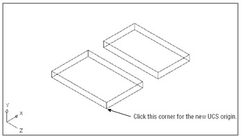
Figure 16.4: Setting up a UCS
Saving a UCS
After you've gone through the work of creating a UCS, you might want to save it, especially if you think you'll want to come back to it later. Here's how to save a UCS:
-
Click the Display UCS Dialog tool on the UCS toolbar to open the UCS dialog box. You can also choose Tools Named UCS.
-
Make sure the Named UCS tab is selected, and then highlight the Unnamed option in the Current UCS list box.
-
Right-click Unnamed and then choose Rename from the shortcut menu. The item changes to allow editing.
-
Type 3DSW
for the name of your new UCS. -
Click OK to exit the dialog box.
Your UCS is now saved with the name 3DSW. You'll be able to recall it from the UCS dialog box or by using other methods that you'll learn about later in this chapter.
Working in a UCS
Next, you will want to arrange the seat and back and draw the legs of the chair. Your UCS is oriented so that you can easily adjust the orientation of the chair components. As you work through the next exercise, notice that while you are manipulating 3D objects, you are really using the same tools you've used to edit 2D objects.
Follow these steps to adjust the seat and back and to draw legs:
-
Click the seat back to expose its grips.
-
Click the bottom grip, as shown in the first image in Figure 16.5.
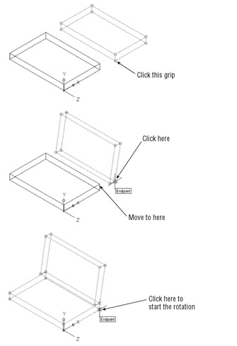
Figure 16.5: Moving the components of the chair into place -
Right-click the mouse to open the Grip Edit shortcut menu.
-
Choose Rotate from the menu. Notice how the seat back now rotates with the movement of the cursor. Take a moment to play with this rotation, because it might take a while to grow accustomed to it. Because this is an Isometric view, you can see an optical illusion effect.
-
Type 80
to rotate the seat back 80 °. Your view will look like the second image in Figure 16.5. -
Click the bottom grip, as shown in the second image in Figure 16.5.
-
Right-click the mouse again and choose Move.
-
Using the Endpoint Osnap, click the top corner of the chair seat to join the chair back to the seat, as shown in the second image in Figure 16.5.
-
Click both the chair seat and back; then click the bottom-corner grip of the seat, as shown in the third image in Figure 16.5.
-
Right-click the mouse and then choose Rotate from the Grip Edit shortcut menu.
-
Enter “10
to rotate both the seat and back a minus 10 degrees. Press the Esc key twice to clear the grips. Your chair will look like Figure 16.6. 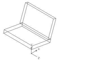
Figure 16.6: The chair after rotating and moving the components
The new UCS orientation enabled you to use the grips to adjust the chair seat and back. All the grip rotation in the previous exercise was confined to the plane of the new UCS. Mirroring and scaling will also occur in relation to the current UCS.
ACAD only LT does not have the 3D Face tool. If you are using LT, skip to the next exercise to find out how to create the additional surfaces to the chair seat and back.
Now, to finish the chair seat and back, add 3D Faces to their top and bottom surfaces:
-
To help you visualize what's going on as you add the 3D Faces, turn on the Hidden Shade mode by choosing View Shade Hidden. Or, if you have the Shade toolbar open, you can click the Hidden tool.
-
 Click the 3D Face button on the Surfaces toolbar or choose Draw Surfaces 3D Face to draw surfaces over the top sides of the chair seat and back. For the chair seat, start the 3D Face in the leftmost corner and work in a counterclockwise fashion, as shown in Figure 16.7. For the chair back, you can start at any corner as long as you select points sequentially around the edge.
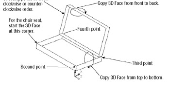
Figure 16.7: The 3D view of your drawing so far, showing where to pick points for the 3D FacesTip To display the Surfaces toolbar, right-click any toolbar and choose Surfaces from the shortcut menu. If you need help with the 3DFace command, see Chapter 15.
-
Copy the 3D Faces to the bottom of the chair seat and to the reverse of the chair back, as shown in Figure 16.7.
-
When you've finished adding the 3D Faces, turn off the Hidden Shade mode. Choose View Shade 2D Wireframe.
Normally, when you're picking points for 3D Faces, it doesn't matter where you start. But for the purpose of this tutorial, you selected points for the seat's 3D Face by starting at the leftmost corner and working in a counterclockwise fashion. The way you create the chair seat will influence the action of some UCS command options, which you'll use later in this chapter.
LT only Because LT users do not have the 3D Face available, you'll need to employ a slightly different method for adding the surfaces:
-
Enter Shademode
H . -
Type UCS
ob and then click the rectangle representing the seat. -
Select the Rectangle tool from the Draw toolbar and use Endpoint Osnap to place a rectangle on the top surface of the seat. The rectangle might blend in with the seat so you won't see it right away.
-
 Click the Region tool in the Draw toolbar and select the rectangle you just drew. Press to complete your selection.
 -
Repeat the steps ”only this time in step 1, click the rectangle representing the back of the seat.
-
To return to a Wireframe view, enter Shademode
2D .
Now you need to return to the UCS you created earlier in order to get back in sync with the rest of the tutorial:
-
Choose Tools Named UCS.
-
Select 3DSW from the list box and then click Set Current.
-
Click OK to exit the dialog box.
You used the command-line version of the UCS command's Object option. You'll learn more about this option later in this chapter. You also used the Region tool, which you'll learn more about in Chapter 18. Basically, the Region tool converts a closed polyline into a special kind of flat surface.
| |
If the UCS icon is not behaving as described in the exercises of this chapter, chances are that its settings have been altered . You can control the behavior of the UCS icon through the UCS dialog box. To open the UCS dialog box, choose Tools Named UCS. You can also click the Display UCS Dialog tool on the UCS II or UCS toolbar. After you've opened the dialog box, click the Settings tab.
The settings in the UCS Icon Settings group affect the way the UCS icon behaves. Normally, the On and Display At UCS Origin Point check boxes are selected. If On is not selected, you won't see the UCS icon at all. If the Display At UCS Origin Point check box is not selected, the UCS icon will remain in the lower-left corner of the drawing window, no matter where its origin is placed in the drawing.
If you have multiple viewports set up in a drawing, you can set these two options independently for each view- port. The third option, Apply To All Active Viewports, forces the first two settings to apply in all viewports.
Two more options appear in the UCS Settings group. If you have multiple viewports open, the Save UCS With Viewport option enables AutoCAD to maintain a separate UCS for each viewport. The Update View To Plan When UCS Is Changed option forces the display to show a Plan view of the current UCS. This means that if you change a UCS orientation, AutoCAD will automatically show a Plan view of the new UCS orientation. This option also forces viewport views to show the extents of Plan views; so if you find that your views are automatically zooming to extents when you don't want them to, turn this setting off.
Another tool for controlling the UCS icon is the UCS Icon dialog box. To open it, enter Ucsicon ![]() P
P ![]() .
.
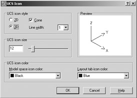
By using this dialog box, you can fine-tune the appearance of the UCS icon, including size and color . The 2D radio button in the UCS Icon Style group changes the UCS icon to the old-style UCS icon used in earlier versions of AutoCAD.
| |
Using Viewports to Aid in 3D Drawing
In Chapter 12, you worked extensively with AutoCAD's floating viewports in Paper Space. In this section, you will use tiled viewports to see your 3D model from several sides at the same time. This is helpful in both creating and editing 3D drawings because it enables you to refer to different portions of the drawing without having to change views.
Tiled viewports are created directly in Model Space, as you'll see in the following exercise:
-
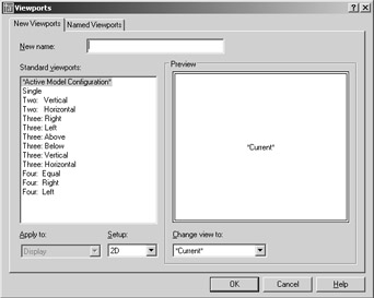
Choose View Viewports Named Viewports to open the Viewports dialog box.
-
Make sure the New Viewports tab is selected, and then select Three: Right from the Standard Viewports list on the left. The window on the right changes to display a sample of the view- port configuration. It shows three rectangles, which represent the viewports, arranged with two on the left and one larger one to the right. Notice that each rectangle is labeled as Current. This tells you that the current view will be placed in each viewport.
-
Open the Setup drop-down list at the bottom of the dialog box and select 3D. Now notice that the labels in the viewport sample change to indicate Top, Front, and SE Isometric. This is close to the arrangement that you'll want, but you need to make one more adjustment. The viewport to the right, SE Isometric, shows the back side of the chair. You want an SW Isometric view in this window.
-
Click the SE Isometric viewport sample. Notice that the sample viewport border thickens to indicate that it is selected.
-
Open the Change View To drop-down list just below the sample viewports and select SW Isometric. The label in the selected viewport changes to let you know that the view will now contain the SW Isometric view. Notice that the Change View To list contains the standard four Isometric views and the six Orthogonal views. By clicking a sample viewport and selecting an option from the Change View To drop-down list, you can arrange your viewport views in nearly any way you want.
-
To keep this viewport arrangement, enter My Viewport Setup in the New Name input box.
-
Now click OK. Your display changes to show three viewports arranged as they were indicated in the Viewports dialog box (see Figure 16.8).
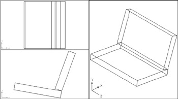
Figure 16.8: Three viewports, each displaying a different view
You've set up your viewport. Let's check to see that your viewport arrangement was saved:
-
Choose View Viewports Named Viewports to open the Viewports dialog box again.
-
Click the Named Viewports tab. My Viewport Setup is listed in the Named Viewports list box. If you click it, a sample view of your viewport arrangement appears on the right.
-
After you've reviewed the addition to the Named Viewports list, close the dialog box.
Now take a close look at your viewport setup. Notice that the UCS icon in each of the two Orthogonal views in the two left viewports are oriented to the plane of the view. AutoCAD enables you to set up a different UCS for each viewport. The top view uses the WCS because it is in the same plane as the WCS. The side view has its own UCS, which is parallel to its view. The Isometric view to the right retains the UCS you saved ”namely the 3DSW UCS.
| Warning | LT users will see the UCS icon oriented to the current UCS and not aligned with the orthogonal view- port views. |
Another Viewports dialog box option you haven't tried yet is the Apply To drop-down list in the New Viewports tab.
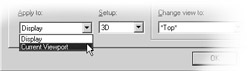
This list shows two options: Display and Current Viewport. When Display is selected, the option you choose from the Standard Viewports list applies to the overall display. When Current Viewport is selected, the option you select applies to the selected viewport in the sample view in the right side of the dialog box. You can use the Current Viewport option to build multiple viewports in custom arrangements.
Adding the Legs
The next items you will add to your chair are the legs. Before you do that, you'll want to set up the 3DSW UCS in the side view of your chair:
-
Click the lower-left viewport to make it active.
-
Click the Display UCS Dialog tool on the UCS toolbar.
-
Click the Named UCSs tab, and then select 3DSW from the list of UCSs.
-
Click the Set Current button. The triangular marker to the left of the UCS names moves to 3DSW.
-
Click OK.
Now you're ready to draw the legs by using the coordinate information shown in Figure 16.9.
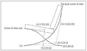
Figure 16.9: Drawing the legs of the chair. Metric coordinates are shown in brackets.
-
Go to the side view of the chair, and move the chair seat and back vertically in the y-axis 8.5 ² , or 21.6 cm for metric users. Make sure you select all the lines and 3D Faces for the move. You might have to pan the view down so that the entire chair is displayed.
Tip If you anticipate moving a group of 3D objects frequently, use the Group command to group objects together. The Group command is especially useful in 3D work, because you can group sets of objects together for easy manipulation yet you can still edit the individual objects within a group.
-
Draw two curved polylines, as shown in Figure 16.9. You might have to adjust your view so that you can draw the legs more easily. You don't have to be absolutely perfect about placing or shaping these lines.
-
Use the grips of the polylines to adjust their curve, if necessary.
-
Choose Modify Object Polyline to give the polylines a width of 0.5 ² ( 1.27 cm for metric users).
-
Use the Properties palette to give the polylines a thickness of “2 ² (minus 2 inches). Metric users should make the thickness “5 cm . Notice that as you draw and edit a polyline, it appears in both the Plan and 3D views.
-
Close the Properties palette when you are finished changing the thickness property.
Tip Polylines are the best objects to use for 3D, because you can generate complex shapes easily by giving the polylines thickness and width.
You have the legs for one side. The next step is to make a mirrored copy of those legs for the other side:
-
Click the top view of the chair in the upper-left viewport.
-
Turn the Ortho mode on, and then click the Mirror tool on the Modify toolbar.
-
In the upper-left viewport, click the two polylines representing the chair legs, and then press
. -
At the Specify first point of mirror line: prompt, use the Midpoint Osnap and select the midpoint of the chair seat, as shown in Figure 16.10.
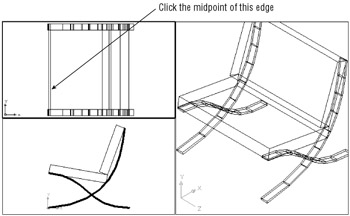
Figure 16.10: Mirroring the legs from one side to another -
At the Specify second point of mirror line: prompt, pick any location to the right of the point you selected so that the rubber-banding line is exactly horizontal.
-
Press
at the Delete source objects? prompt. The legs are mirrored to the opposite side of the chair. Your screen should look similar to Figure 16.10.
Notice that the broken-pencil UCS icon has shifted to the viewport in the lower-left corner. This icon tells you that the current UCS is perpendicular to the plane of that view.
Your chair is now complete. Let's finish by getting a better look at it:
-
Click the viewport to the right showing the Isometric view.
-
Open the Viewport dialog box and click the New Viewport tab.
-
Select Single from the Standard Viewports list and then click OK.
-
Use the Zoom tool to adjust your view so that it looks similar to Figure 16.11.
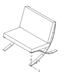
Figure 16.11: The chair in 3D with hidden lines removed -
Choose View Hide to get a view of your chair with the lines hidden, as shown in Figure 16.11.
Controlling the UCS
You've seen how to select a UCS from a set of predefined UCSs. You can frequently use these preset UCSs and make minor adjustments to them to get the exact UCS you want.
You can define a UCS in other ways. You can, for example, use the 3D Face of your chair seat as the definition for a UCS. In the following set of exercises, you will get some practice moving your UCS around. Learning how to move effortlessly between UCSs is crucial to mastering the creation of 3D models, so you'll want to pay special attention to the command options shown in these procedures. These options are accessible from either the Tools UCS cascading menu or the UCS toolbar.
UCS Based on Object Orientation
You can define a UCS based on the orientation of an object. This is helpful when you want to work on a predefined object to fill in details on its surface plane. Follow these steps to define a UCS in this way:
-
 Click the Object UCS tool on the UCS toolbar or choose Tools New UCS Object. You can also type UCS OB .
 -
At the Select object to align UCS: prompt, pick the 3D Face used to define the top surface of the chair seat. Because the 3D Face and the polyline outline of the seat share a common edge, you might need to use the Selection Cycling feature to pick the 3D Face. The UCS icon shifts to reflect the new coordinate system's orientation (see Figure 16.12).
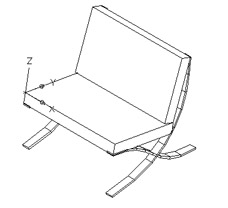
Figure 16.12: Using the Object option of the UCS command to locate a UCSTip If you have a hidden-line view, selection cycling will not work for picking 3D Faces. Issue a Regen to return to a Wireframe view.
Orientation of the UCS Origin
Remember earlier in the chapter when you drew the 3D Face for the seat in a specific way? Well, the location of the UCS origin and its orientation depend on how that 3D Face was created. If you had drawn it other than as instructed, the UCS you defined by using the Object option in the previous exercise would not have been generated as described.
Table 16.1 describes how an object can determine the orientation of a UCS.
| Object Type | UCS Orientation |
|---|---|
| Arc | The center of the arc establishes the UCS origin. The x-axis of the UCS passes through the pick point on the arc. |
| Circle | The center of the circle establishes the UCS origin. The x-axis of the UCS passes through the pick point on the circle. |
| Dimension | The midpoint of the dimension text establishes the origin of the UCS origin. The x-axis of the UCS is parallel to the x-axis that was active when the dimension was drawn. |
| Line | The endpoint nearest the pick point establishes the origin of the UCS, and the x-z plane of the UCS contains the line. |
| Point | The point location establishes the UCS origin. The UCS orientation is arbitrary. |
| 2D polyline | The starting point of the polyline establishes the UCS origin. The x-axis is determined by the direction from the first point to the next vertex. |
| Solid | The first point of the solid establishes the origin of the UCS. The second point of the solid establishes the x-axis. |
| Trace | The direction of the trace establishes the x-axis of the UCS, and the beginning point sets the origin. |
| 3D Face | The first point of the 3D Face establishes the origin. The first and second points establish the x-axis. The plane defined by the 3D Face determines the orientation of the UCS. |
| Shapes, text, blocks, attributes, and attribute definitions | The insertion point establishes the origin of the UCS. The lishes the x-axis. |
UCS Based on Offset Orientation
At times you might want to work in a UCS that has the same orientation as the current UCS but is offset. For example, you might be drawing a building that has several parallel walls offset with a sawtooth effect (see Figure 16.13).
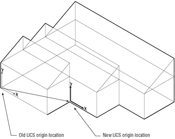
Figure 16.13: Using the Origin option to shift the UCS
You can easily hop from one UCS to a parallel UCS by using the Origin option:
-
Click the Origin UCS tool on the UCS toolbar or choose Tools New UCS Origin. You can also type UCS
O . -
At the Specify new origin point <0,0,0>: prompt, pick the bottom end of the chair leg, just below the current UCS origin. The UCS icon shifts to the end of the leg, with its origin at the point you picked (see Figure 16.14).
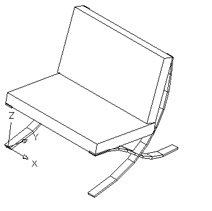
Figure 16.14: Moving the origin of the UCS
Moving versus Creating a UCS Origin
The Origin UCS tool creates a new UCS that you can save under its own name. A similar option is Move UCS on the Tools pull-down menu. At first glance, they seem to do the same thing; that is, they create a new UCS by moving an existing UCS's origin. There is a subtle difference between the two, however. The Tools Move UCS option is intended to move an existing named UCS to a new location. It doesn't actually create a new one. For example, if you use Move UCS to move the 3DSW UCS you created earlier in this chapter, 3DSW will appear in its new location when you recall it. On the other hand, if you use the Origin UCS tool to change the origin of the 3DSW UCS, AutoCAD creates an entirely different UCS and maintains the original location of 3DSW.
The Tools Move UCS option can also be found on the UCS II toolbar. You'll get a chance to work with the UCS II toolbar in the next section.
UCS Rotated Around an Axis
Now suppose you want to change the orientation of the x-, y-, or z-axis of a UCS. You can accomplish this by using the X, Y, or Z Axis Rotate UCS options on the UCS toolbar.
Let's try rotating the UCS about the z-axis to see how this works:
-
 Click the Z Axis Rotate UCS tool on the UCS toolbar or choose Tools New UCS Z. You can also type UCS Z . This will enable you to rotate the current UCS around the z-axis.
 -
At the Specify rotation angle about Z axis <90>: prompt, press
to accept the default of 90 °. The UCS icon rotates to reflect the new orientation of the current UCS (see Figure 16.15). 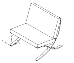
Figure 16.15: Rotating the UCS about the z-axis
Similarly, the X and Y Axis Rotate UCS options enable you to rotate the UCS about the current x- and y-axis, respectively, just as you did for the z-axis earlier. The X and Y Axis Rotate UCS tools are helpful in orienting a UCS to an inclined plane. For example, if you want to work on the plane of a sloped roof of a building, you can first use the Origin UCS tool to align the UCS to the edge of a roof and then use the X Axis Rotate UCS tool to rotate the UCS to the angle of the roof slope, as shown in Figure 16.16. Note that the default is 90 °, so you only have to press ![]() to rotate the UCS 90 °, but you can also enter a value at the Specify another rotation angle: prompt.
to rotate the UCS 90 °, but you can also enter a value at the Specify another rotation angle: prompt.
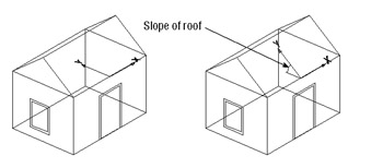
Figure 16.16: Moving a UCS to the plane of a sloping roof
Finally, you can skew the UCS by using the Z Axis Vector option. This is useful when you need to define a UCS based on a z-axis determined by two objects. Here are the steps:
-
 Click the Z Axis Vector UCS tool on the UCS toolbar or choose Tools UCS Z Axis Vector. You can also type UCS ZA .
 -
At the Specify new origin point <0,0,0>: prompt, press
to accept the default, which is the current UCS origin. You can shift the origin point at this prompt if you like. -
At the next prompt
Specify point on positive portion of Z-axis <0 ¢ -0 ² , 0 ¢ - 0 ² , 0 ¢ -1 ² >:
use the Endpoint Osnap override and pick the other chair leg end, as shown in Figure 16.17. The UCS twists to reflect the new z-axis of the UCS.
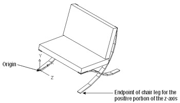
Figure 16.17: Picking points for the Z Axis Vector optionWarning Because your cursor location is in the plane of the current UCS, it is best to pick a point on an object by using either the Osnap overrides or the coordinate filters.
Orienting a UCS in the View Plane
Finally, you can define a UCS in the current view plane. This is useful if you want to switch quickly to the current view plane for editing or for adding text to a 3D view.
![]() Click the View UCS tool on the UCS toolbar or choose Tools New UCS View. You can also type UCS
Click the View UCS tool on the UCS toolbar or choose Tools New UCS View. You can also type UCS ![]() V
V ![]() . The UCS icon changes to show that the UCS is aligned with the current view.
. The UCS icon changes to show that the UCS is aligned with the current view.
AutoCAD uses the current UCS origin point for the origin of the new UCS. By defining a view as a UCS, you can enter text to label your drawing, just as you would in a technical illustration. Text entered in a plane created in this way appears normal.
Now you've finished your tour of the UCS command. Set the UCS back to the World Coordinate System and save the Barcelon.dwg file.
You've explored nearly every option in creating a UCS, except for one. In the next section, you'll learn about the 3 Point option for creating a UCS. This is the most versatile method for creating a UCS, but it is a bit more involved than some of the other UCS options.
Saving a UCS with a View
AutoCAD 2000 introduced the ability to save a UCS with a view. Choose View Named Views to open the Views dialog box, and then click the Named Views tab . Click the New button to open the New View dialog box. Enter a name for your new view; then make sure the Save UCS With View check box is selected. By default, AutoCAD saves the current UCS with the view. You can also choose a UCS to save with a new view by using the UCS Name drop-down list.
EAN: 2147483647
Pages: 261