Physical Cable Types
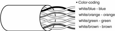
| Much attention is given to the specifications used for Ethernet and Token-Ring networks. Most of these specifications deal with the physical makeup of the cabling involved in connecting the individual components of the network. Understanding the cable types, the number of wires in a cable (both shielded and unshielded varieties), and several other electrical factors is critical to successfully upgrading or maintaining your network system. The type of cable you use depends on the type of LAN you are creating. The connectors, terminations, and distances that can be covered by particular cable types will be a factor in determining any cable length restrictions and overall quality of LAN you can create. For example, an Ethernet network card and a Token-Ring network adapter card use different connectors and cables. Twisted-Pair CablingThe most basic wire type used for LAN wiring is twisted-pair wiring. This wire type also is referred to as unshielded twisted pair, or UTP. This wire is a derivative of the more common cable that was used in telephone installations in most commercial facilities for years. This type is versatile, is easy to install, and has favorable performance characteristics. It comes in various colors, wire gauges, insulation materials, twisting methods, and outer jacket materials. The basic cable assembly for UTP cable can contain a large number of conductors (or copper wires). Most conductors are grouped into pairs that are twisted around each other. Telephone cables are available in 2, 4, 6, 25, 100, and even larger groupings of conductors. Most of the cable that is used for LAN wiring comes as cable consisting of four pairs of wires. The four-pair cable has become a standard and is referenced in the EIA/TIA-568B cabling standards. This is the cable around which most of the cable standards and performance tests are based. Several of the LAN topology configurations use only two of the four-wire pairs; however, some use all four pairs. Another common cable type that is found in twisted-pair installations is a 25-pair jumper cable. This cable type is primarily used between patch panels and connector type punchdown blocks. Note A punch block is a big rack with wires coming out of it that connects to various other devices, such as switches. You then take cables, such as those that extend to the desktop, and plug them into one of the sockets on the punchdown block. This is similar in concept to what you might find in a telephone communications room, though some of those "wrap" the wire instead of "punching" it into a slot. The main difference between typical telephone wiring and LAN wiring is the grading of the assembly of the twisted pairs within the cable. The primary factor that differentiates one cable type from another is the number of twists per foot that each individual pair of conductors has within the cable. The twisting of the individual pairs to the cable is significant. The twisting of the two wires has a twofold effect electrically on the cable assembly. First, it causes the interline capacitance to be reduced. This is a good thing because the reduction of capacitance reduces any signal shorting between the conductors at high frequencies. Second, twisting the wire couples the electromagnetic fields equally, thus helping to cancel out any interfering signals. This operation is referred to as a balanced transmission. One effect of achieving a balanced transmission is that the high frequencies of a LAN signal do not interfere with the other use of the wires in a cable assembly. Some radiation of the signal does occur, but because the transmitted signal is kept to a low amplitude, random emissions remain within acceptable limits. Typically, wire sizes for UTP cable range between 18 AWG and 32 AWG. AWG, which stands for American wire gauge, is the standard for sizing wires in the U.S. Wire size is based primarily on the current-carrying capacity of the wire as set by the National Electrical Code. As the wire gauge increases, the physical diameter of the wire decreases. So a number 10 AWG wire is physically smaller than a number 8 AWG wire. Number 10 AWG wire is approximately 0.1 inch in diameter and usually can carry approximately 30 amps of current. So for telephone wiring or LAN wiring, the number 18 AWG wire is much larger than the 32 AWG wire. Common sizes for LAN wiring are typically 22 to 24 AWG. This wire is typically solid, not stranded, for ease in termination on insulation displacement connectors. Categories of Twisted-Pair CablesAs mentioned previously, the twisting of the wire pairs of conductors that make up cables is importantso important that the cable used for LAN wiring is graded into categories. Category 1 was used for POTS (or plain old telephone service). Category 2 was used in early networking wiring schemes, such as ARCnet, and for connecting terminals to multiuser computer networks. Category 3 uses four twists per foot and is still graded for operating as a LAN wiring system. Category 3 is rated for speeds up to 16MHz and is still used as a cable in some Token-Ring networks. Category 4 is rated up to 20MHz. Category 5 is rated for up to 100MHz operation. Category 5 was, until recently, the de facto standard for LAN wiring; however, it has now been replaced by two new categories: Category 5e and Category 6. Category 5E differs from Category 5 in that it adheres to standards 568B.1 and B.2 and additional Class D requirements of the ISO/IEC 11801. These standards require a tunable frequency limit of 100MHz and are a superset of Category 5 and Class D. During the first quarter of 2001, Category 6 cabling was certified for use as a standard. Transmission characteristics are specified up to 250MHz. Also called Class E according to ISO/IEC, this cable probably will represent the last generation of unshielded twisted-pair cabling that is used in LAN wiring. This cable is different from the standard UTP cable because it contains filler material to separate the twisted pairs from each other, and thereby reduces cross-talk between wire pairs. One of the biggest problems with using higher frequencies through the pairs of the cables is that adjacent conductor capacitance is reduced and cross-talk increases. Separating these conductors reduces this capacitance and cross-talk. This also is a consideration when installing cables because if cables are bundled too tightly there can be a resulting chance of interference of data signals between individual cables. Hence, modern standard practice dictates that when cables are installed, they are to be installed with either loose cable ties or Velcro straps. The latest category, Category 7 UTP cabling, offers a different approach to twisted-pair cabling architecture. The cable is assembled with an overall shield and individually shielded pairs. The most significant improvement with this type of cable will be in the higher performance bandwidth achieved with ratings up to 600MHz. It is also designed to be backward-compatible with lower-performance categories and classes, although it appears it will have a new interface for the jack and plug. It is interesting to note that TIA is not actively developing a standard for Category 7. This organization probably will try to assimilate a standard with class F standards put forth by the ISO. Performance ComparisonThe choice of cabling insulation material is important. Requirements set forth in the National Electrical Code (NEC) specifically and stringently place requirements on the type of cable insulation allowed in certain portions of buildings. There's an increasing use of large amounts of cable for LAN wiring, and these cables are usually installed above drop ceilings and below computer-room raised floors (also known as the plenum space). Unfortunately, these areas are most often used to handle cooling and environmental air. Conventional wire installations installed in these locations were found to be flammable at the very least, and at their worst, would produce toxic gases from the materials that surround cable bundles that would be carried with the cooling or environmental air, thus placing people in the other parts of the building at risk. Additionally, fire can actually be spread through the plenum areas. Manufacturers soon developed cable installations that were less flammable and could be used in plenum-rated areas. The National Electrical Code differentiates cable types by voltage, power classifications, and insulation types. It should be noted that there is a definite difference between plenum- and riser-rated cable. It would seem that riser-rated cable would be classified higher than plenum-rated cable, because riser-rated cable is intended for use in vertical shafts that run between floors. The shafts are not normally used to handle environmental or cooling air except in ductwork. Thus, the cable installed in risers does not have to have insulation rated as stringently as that for cabling installed in plenum-rated areas. The special requirements for cabling insulation and power ratings are covered in detail in the NFPA National Electrical Code Sections 770 and 800, for those who want to pursue these details further. Color Coding and MarkingEach pair of wires in a twisted-pair cable assembly is color coded so that each wire can be identified at each end of the cable assembly and terminated properly. This color code is shown in Figure 6.5. Figure 6.5. Wire pairs in a cable are color coded. As you can see, each pair of the cable is color coded in a complementary fashion. Pair-one wires are color coded white-blue and blue-white. The blue-white wire has as its base color blue insulation with a white stripe molded at intervals along its length. The stripe is sometimes called a tracer. The white-blue wire is color coded in reverse, with a white wire that has a blue tracer. The color code is unique for each pair and is repetitive. The color coding is important in LAN wiring because the system signals are polarity sensitive. If pairs on the cable are reversed, the signals are reversed, causing a failure in the receiving equipment. The terms tip and ring, used to designate the polarity of each pair of wires, stem from the days of the old telephone patch panels. The equipment used consisted of quarter-inch phone plugs, which fit into corresponding jacks on a patch board or switchboard. The switchboard plug consisted of two parts. The tip of the plug was wired through the sleeve or ring of the plug. The plug used on audio equipment and musical instruments is the same plug. The primary color was wired to the ring and the secondary color was wired to the tip. As mentioned before, there is also a use for 25-pair jumper cable. This color code, broken down by pair, is shown in Table 6.1.
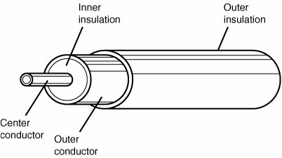
This cable must be rated for the category for which it's to be used. Physically, it mostly is used between patch panels and punchdown blocks, or between patch panels to patch panel installations. Cable sizes above 25 pairs are usually in groups of 25-pair cables. Each of these groups of cables is marked within the larger bundle with a wrapped colored leader that, by design, is color coded with the same color code that is used on the twisted-pair cabling scheme. Thus, on a 50-pair cable, which would have two 25-pair cables, the 25-pair bundle has an outer spiral wrap of a blue plastic streamer, and the second group of 25 has a group wrapped with an orange streamer. This color code can be repeated ad infinitum for a very large group of 25-pair cables. Coaxial CablesCoaxial cables are the original LAN cable. This cable was first used in Ethernet networks, IBM PC net broadband networks, and ARCnet networks, besides being used for video and cable television applications. It still is in use in many older locations, even though newer installations have converted to twisted pair. Coaxial cable has been around long enough that it has a mature construction technology and is relatively inexpensive. The primary advantages of coaxial cable are its self-shielding properties, its low attenuation at high frequencies, and its moderate installation expense. For example, if you have a cable modem in your house, a coaxial cable is used for both the video signals and the cable modem frequencies. Coaxial cables consist of the conductor centrally positioned in a cable surrounded by an insulating medium, which then is enclosed by a shield (see Figure 6.6). The shield can consist of a foil wrapping within an integral drain wire or a wire braid. The coax that is used for thick Ethernet might have a double-shield layer. Figure 6.6. Coaxial cable consists of a shielded copper wire. Placing the center conductor in an insulating medium surrounded by a shielding material theoretically traps all the electromagnetic fields inside the cable assembly. Because this shield has to be grounded, the mode of propagation of the signals in the cable is analogous to that of a mechanical pipeline. The grounded shield helps prevent interfering signals outside the cable from impinging on the center conductor. Conversely, the grounded shield also prevents signals from leaking out of the cable structure. Grounding is very important in this cabling system. A cable installation without proper grounding is susceptible to outside EMI and RFI interference. Types of Coaxial CablingTwo types of coax cabling are used in wiring local area networks. One type is called thicknet and the other is referred to as thinnet. Thicknet was used in the original Ethernet coax trunk distribution cable now known as 10BASE-5. The cable has a large center diameter conductor of number 12 AWG and has an overall diameter of approximately 0.4 inch. This cable typically was run close to a workstation either in the ceiling or in the walls. A connection is made to the cable by literally tapping to the wire by punching a hole through it (commonly known as a vampire tap), and then the connection is directly made by running a cable from the tap to the networked device, such as a terminal or a PC. The term thicknet was introduced because this coaxial cable is almost a half-inch in diameter, and when newer, smaller diameter coaxial cable was introduced it looked very large. A newer standard cable, which is approximately a quarter-inch diameter and is much more flexible, was named thinnet (10BASE-2). This type of cable uses BNC connectors with T-adapters. It is less expensive, but the distances for a thinnet Ethernet segment are limited compared to those for thicknet. ARCnet is another LAN topology that uses coaxial cable. In this topology, the workstations are connected directly to the coax in a star arrangement. Each leg terminates in an active or a passive hub. ARCnet is one of the oldest networking technologies still in use today, although you're more likely to find it used in point-of-sale mechanisms, linking electronic cash registers, for example, than in other types of networks. Typically, the sizes for coaxial cables are designated by an RGB number or a manufacturer's numbering system. A summary of cable types follows:
Characteristic ImpedanceAs you can see from the preceding list, the characteristic impedance is the first electrical consideration mentioned. This is because this cable was first used for the needs of RF signal propagation, and the coax impedance was specified so that proper load matching could be made at the head end of the RF equipment. Standard impedances for coaxial cable are 50 ohms, 75 ohms, and 92 ohms. The diameter of the center conductor, the dialectic material, and the mechanical properties of the shield contribute and also help define the coaxial cable's characteristic impedance. This impedance value is the value of the impedance at the maximum frequency for which the cable is designed. For example, if you were using coaxial cable for video service, you would expect to see 75-ohm impedance exhibited at the maximum operating frequency of 900MHz. For cable, there's always a trade-off between frequency headroom and attenuation per cable length. Typically for most coax cable, the attenuation is less than 1.5 decibels per hundred feet at 10MHz. At 100MHz, the attenuation is up around 5 decibels per hundred feet; consequently, as you increase your cable run, your attenuation goes up. When installing coax, there's always a tradeoff in signal strength versus cable length versus frequency bandwidth. A 10Mbps Ethernet segment can be up to 500 meters or approximately 1,640 feet in length using thicknet cable. For thinnet cable, the length can be up to 185 meters or 607 feet. Attenuation and frequency-based signal distortion limit segment lengths in Ethernet systems, whereas network lengths are limited by timing constraints that will be seen as bit-rate errors. Of course, at 100MB per second the maximum length is again reduced.
The two most common types of connectors are the BNC and the TNC. These are both named after their designers. The BNC connector has been around since World War II. It is a bayonet type and can be installed as a crimp type, a three-piece type, or a screw-on connector. BNC connectors are similar to those used by cable companies to connect coax cabling to your set-top box. There is a single wire in the middle of the connector that carries the signal. To attach this connector to a cable, a crimping tool is used. A small portion of the cable is peeled back and inserted into the rear of the connector. The crimping tool then applies pressure to hold the cable to the connector. A three-piece type looks like a T-shaped connector, so you can connect cables to each side of the connector and use the third to screw into the receptacle on your computer. This last type was crucial in allowing a connection to a computer using coax cabling, yet letting the signal flow through the connector if the third part of the connector was removed from the computer. The TNC connector usually is configured as a screw-on type and has been specifically developed for ease of installation with video-type cable. It is not used much in computer networking. These are the advantages of coaxial cables:
These are the disadvantages of coaxial cable:
Note Coaxial cables are rarely used in LANs today. However, the development of cable modems has given a new life to these cables, when applied to networking. Just as your cable television uses coaxial cables, cable modems also use frequencies on these cables to transmit and receive data to and from the Internet. Fiber-Optic CablesFiber-optic technology is significantly different from copper and uses light transmitted through hair-thin fibers. Fiber-optic cable offers higher bandwidth and lower signal losses. It also allows higher data rates over longer distances. These are the advantages of using fiber-optic cables:
The biggest drawback in using copper cable is that signal loss increases with signal frequency. Attenuation, or signal loss, is higher at 100MHz than at 10MHz. Consequently, high data rates increase power loss and decrease practical transmission distances. Loss does not significantly change with signal frequency in fiber-optic systems. Attenuation does change with frequency of the light transmitted through the fiber, but the data rate does not. So if you have both a 10MHz and a 100MHz signal traveling through the fiber, they are attenuated alike. Electromagnetic ImmunityThe basic transmission medium in a fiber-optic cable consists of either plastic or glass material. Both of these are considered to be insulators or dielectrics, so these materials are immune to electromagnetic interference. The transmitted signals consist mainly of modulated light signals that are tunneled through the fiber medium and do not escape. No signals emanate outside the cable, so it does not cause cross-talk, which is the main limitation in twisted-pair cable. It can be run in electrically noisy environments such as high-density computer-room installations, factory floors, and other electrically dense environments without concern because the cables are immune to outside noise sources. Yet, as you will learn in other chapters, fiber-optic cables do suffer some signal interference within the cable itself. For example, single-mode fiber, in which only one signal is transmitted, can cover a longer distance than multi-mode fiber, which injects multiple modes of light into a larger fiber-optic cable. In such a case, multi-mode fiber can suffer from degradation of the signal as different wavelengths of light interfere with other wavelengths. Size and WeightFiber-optic cable weighs considerably less than copper cable. It is typically 22% to 50% lighter than comparable four-pair Category 5 cable. Less weight makes fiber-optic cable easier to install depending on its durability, which has improved over time. Typical weights for 1,000 feet are as listed here:
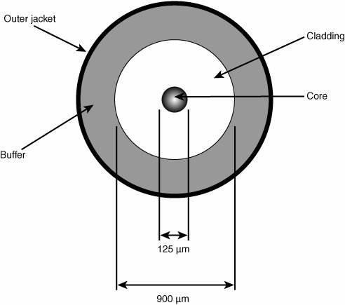
Fiber-optic cable is smaller than copper cable. Typically, it's about 15% less in volume than Category 5 twisted-pair cable. SafetyAs stated before, the glass and plastic that compose the transmission medium of fiber-optic cable are dielectrics, or insulators, and thus do not conduct electricity. Fiber-optic cable therefore does not present a spark hazard and can be used in explosive environments. It also does not attract lightning. Fiber-optic cable has jacket ratings that are comparable to the copper cable jackets and has the same flammability ratings that meet code requirements in buildings. SecurityIt wasn't until just recently that the capability to physically tap fiber-optic cables was developed. This requires extremely expensive equipment and a skilled operator. Typically, because fiber-optic cables do not emanate electromagnetic radiation, they are fairly secure against tapping. When compared to other methods of transmission, fiber-optic cable is the most secure medium for carrying sensitive data. Fiber Construction and OperationFiber optics is a technology in which signals are converted from electrical into light signals. The signals then are sent or transmitted through a thin glass or plastic fiber and converted back to electrical signals. The fiber-optic cable consists of three concentric layers differing in optical parities. As shown in Figure 6.7, a fiber-optic cable consists of the following:
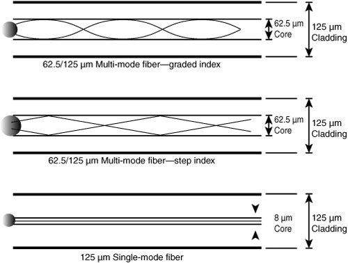
Figure 6.7. Components of a fiber-optic cable. How Light Travels Through a Fiber-Optic CableLight transmission is not random. It is channeled into modes, which are possible paths for light rays to travel. There can be as few as one mode (single-mode fiber) or as many as several thousand modes in the design of the fiber (multi-mode fiber). Although the number of modes is significant, it actually relates to determining the fiber's bandwidth. More modes means lower bandwidth. The cause of this is dispersion. As a pulse of light travels through the fiber, it spreads out over distance. Although there are several reasons for such dispersion, the two principal concerns are modal dispersion and material dispersion. Different path lengths followed by light rays as they bounce down the fiber cause modal dispersion. Material dispersion is caused by different light wavelengths traveling at different speeds. To limit material dispersion, you limit the wavelengths of light transmitted. In other words, don't use multi-mode fiber if you need to transmit a lot of data from one place to another. Use single-mode fiber for long distances. Use several cables of multi-mode fiber when you need to increase the bandwidth, without compromising on the actual bandwidth that can be achieved. Multi-mode fiber does allow for more than one data channel to travel through the same fiber-optic cable, but it should be limited as distance increases. Fiber-optic cable can be modified in several ways to achieve different signal transmission characteristics. Modifications can be made to affect bandwidth and attenuation, and to facilitate coupling the light into and out of the fiber. The stepped index multi-mode fiber has a large core with uniform optical properties. This fiber supports thousands of modes of operation and offers the highest dispersion and, hence, the lowest bandwidth (see Figure 6.8). Figure 6.8. Light can reflect off the internal cladding as it travels through the fiber-optic cable. The graded index multi-mode fiber has different optical properties in the core. This type reduces dispersion and increases bandwidth. The graded index makes light following longer paths travel slightly faster than light following shorter paths. The net result is that the light does not spread out as much. Nearly all multi-mode fiber that is used in networking and data communications has a graded index score. The single-mode fiber has the highest bandwidth and the lowest loss of performance. The core of single-mode fiber is smaller than that of multi-mode fiber. The bandwidth that this fiber exhibits is much greater than the capacities of today's electronics. This fiber can support speeds in excess of many gigabytes per second. The most common fiber for networking is the 62/125-micron fiber (multi-mode). The two numbers designate the core diameter and the cladding diameter, respectively. In this case the core diameter is 62.5 microns and the cladding diameter is 125 microns. Other common sizes are 50/125-micron and 100/140-micron cable. To summarize:
Attenuation in Fiber-Optic CablesSimilar to the degradation of an electrical signal in copper wires, attenuation in fiber-optic cables is a loss of power. During transmission, light pulses lose some of their energy, which shows up as a loss in signal strength. Attenuation is specified for fiber in decibels per kilometer. Attenuation ranges from under one decibel per kilometer for single-mode fibers and up to 2,000 decibels per kilometer for large-core plastic fibers. Attenuation varies with the wavelength of light. There are three prime low-loss windows of wavelengths that are used today:
The 850-nanometer wavelength is the most widely used because it was developed first, and optical devices such as LEDs (light-emitting diodes) operating at 850 nanometers are inexpensive and plentiful. The 1,300-nanometer wavelength offers low loss with a slight increase in cost for LEDs. The 1,550-nanometer wavelength is mainly used in long-distance telecommunications applications. |
EAN: 2147483647
Pages: 411