Structured Wiring
| In the 1980s, the Telecommunications Industry Association (TIA) and the Electronics Industries Association (EIA) formed a task force to establish a set of standards for installing network wiring in buildings. The first draft was completed in 1991 and became known as EIA/TIA-568 (referred to in this chapter as 568). A more recent standard is named ANSI/TIA/EIA-569-A (referred to in this chapter as 569-A). These standards documents encompass structured wiring, cables, network topology, connectors and hardware, electrical performance specifications, physical termination, and support mechanisms. Note ANSI is an acronym for American National Standards Institute. ANSI was founded in 1918 and is the major standards organization for the United States. ANSI is also a member of other standards organizations, such as ISO. Programmers might recognize one of the standards that ANSI adopted many years ago: American Standard Code for Information Interchange (ASCII). Unicode and other standards have been developed to add support for other language character sets. You can find ANSI online at www.ansi.org. The 568 and 569-A standards describe the physical layout and specifications for the physical plant as it relates to the various topological standards. The physical plant, in this context, comprises everything having to do with what leads up to your desktop, from routers, cables, patch panels, and so on. These are the basic topics covered in the standards:
In the following sections you will learn about these topics, as well as others. For a more complete explanation of the standards, it is suggested that you obtain the standards and read them. It is beyond the scope of this book to describe the standards in detail. Instead, those that apply to networks are discussed. In addition, several terms are defined for those who are not well versed in the terminology used by these standards. Many of these terms are also used throughout other chapters in this book. Between this chapter and the glossary, you should be able to locate the definition of almost any word used by network administrators, and those who put together LANs, MANs, and WANs. The Work AreaThe work area includes the telecommunications outlet (that is, the faceplate into which you plug your computer's network cable at your desk), which serves as the work area interface to the entire network cabling system. Work area equipment includes cables used to connect to the telecommunications outlet. The following are the work area cabling specifications:
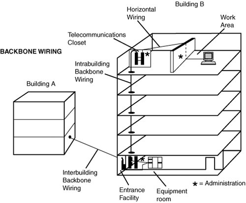
The Backbone Cabling System StructureThe backbone cabling system of the standard provides interconnections between telecommunication rooms, equipment rooms, and entrance facilities (see Figure 6.1). Figure 6.1. The backbone of the network includes the cables that connect different areas of the network. This cabling system includes backbone cables, intermediate and main cross connects, mechanical terminations, and patch cords or jumpers used for backbone-to-backbone cross connections. The backbone also extends between buildings in a campus environment. There are some points specified for the backbone of the cabling system:
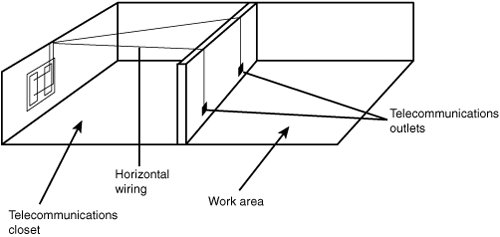
Note that in these specifications, bridge taps and splitters are not allowed. Caution A bridge tap is an extraneous piece of cabling that is left over from a previous connection to a communications line. If not removed, a bridge tap acts similarly to an antenna, and causes impedance mismatches and other problems with the signal that travels down the copper wire. Bridge taps are one of the reasons why it can be difficult to obtain DSL service from your local phone company. As phones are added to your local loop and then disconnected, many dangling wires can be left behind because it's simply too costly to remove them. In a properly cabled network, bridge taps should not exist. Tip Splitters are devices that are used to separate higher frequencies from lower frequencies on a copper wire. Again, splitters serve no purpose on a properly cabled LAN. However, on the public switched telephone network (PSTN), splitters can be installed to make it possible to obtain voice-grade telephone service and DSL service using the same copper wire pair, with a minimum of interference between the frequencies used on the wire for voice and DSL services. For more about DSL, see Chapter 16, "Digital Subscriber Lines (DSL) Technology." The Horizontal Cabling System StructureThe horizontal cabling system (shown in Figure 6.2) extends from the telecommunications outlet in the work area and terminates in a horizontal cross connect in the telecommunications room. It includes the telecommunications outlet. Figure 6.2. The horizontal cabling extends from the telecommunications closet to the user's work area. The distance covered by the horizontal cabling is limited by the network topology chosen for your network. For example, in most Ethernet networks, this distance is 90 meters. Token-Ring has various specifications, depending on the cables used. For more information about Token-Ring, see the chapter "Token-Ring Networks," located on the upgradingandrepairingpcs.com Web site. The Telecommunications ClosetTelecommunications rooms generally are considered to be floor-serving facilities for horizontal cable distribution. They also are used for intermediate and main cross connects. The telecommunications room is where you place patch panels, as well as hubs or switches that are used to connect individual workstations or servers to the network backbone. |
EAN: 2147483647
Pages: 411
- Structures, Processes and Relational Mechanisms for IT Governance
- Assessing Business-IT Alignment Maturity
- Linking the IT Balanced Scorecard to the Business Objectives at a Major Canadian Financial Group
- Measuring and Managing E-Business Initiatives Through the Balanced Scorecard
- Governance Structures for IT in the Health Care Industry