It s Only a Model
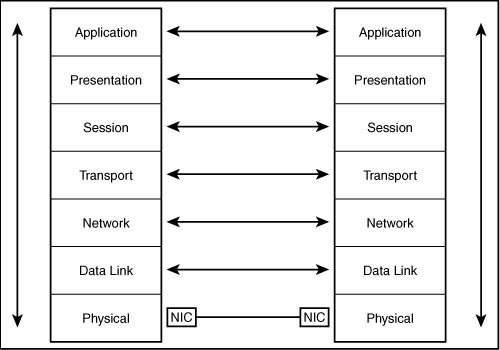
It's Only a Model!The OSI networking model is just thata model. It's a reference you can use when discussing networking with colleagues. The model specifies seven layers, which you can think of as separate modules, each of which performs a specific set of functions. Each layer in the model communicates with adjacent layers in the model using a standard defined interface. Therefore, the internal workings of each layer can be left up to the vendor to develop. All that matters is that all the layers work together, no matter which vendor provides them. For example, network adapters and network cabling fall into the bottom layer, the Physical layer. Network cards are designed to work with the software that falls into the next higher layer, the Data Link layer. Figure A.1 shows how the layers of the model interact with one another, from two ends of a network connection. Figure A.1. Each layer in the OSI reference model provides functions to adjacent layers in the model. As you can see in Figure A.1, arrows show the flow of information down the stack from one computer. When the information reaches the Physical layer, the components at that layer act to deliver the data to the remote system. At the remote system, the Physical layer receives the electrical (or light) impulses, converts them into the appropriate message format, and passes the information back up the stack so that the data eventually reaches the application for which it was intended. Also in Figure A.1 you can see that arrows point both ways between the layers on one system and the corresponding layers on the other system. This implies that from a logical point of view, each layer in the model performs functions as if it were talking directly to its corresponding layer at the remote system. Each layer is unaware of what is going on in layers underneath it or how the message is delivered to the matching layer on the remote machine. For example, TCP breaks up large messages into smaller messages called segments. These segments are then passed to lower layers that encapsulate them in IP datagrams and then into a physical layer protocol, such as Ethernet. On the receiving end, the TCP software does not have to know that Ethernet, Token-Ring, or any other technology was used to deliver the message. Instead, the TCP software on the remote system receives the segments that the TCP software on the sending system originally sent. EncapsulationMost layers attach information to the data that they pass to lower layers. This data is called header information. For example, an IP datagram contains header information such as the source and destination IP addresses and port numbers. When the IP datagram is passed down the stack, it can be encapsulated in an Ethernet frame. An Ethernet frame adds its own header information (refer to Chapter 13, "Ethernet: The Universal Standard"). Here, instead of IP addresses, physical MAC addresses are used in the Ethernet header. On the receiving end of the communication, the Ethernet header information is stripped off before the remaining data is passed up the stack. At the IP level the IP header is removed and the data is passed back up to the TCP software, and so on. Thus, each layer on each computer actually sees, with few exceptions, only the header information that was attached to the original message by the corresponding layer on the other machine. This is how the layers logically interact, regardless of how layers above or beneath operate internally. The following sections describe the functions that are performed at each layer, starting from the bottom (Physical layer) and working up to the top. An important point to remember is that some vendors combine two or more layers into a single software application. As mentioned, the OSI Seven-Layer Reference Model is just that, a model. It's a way to discuss networking technologies in a rational manner that professionals can understand. It does not mean that all networking products must conform to this model! Physical LayerThe Physical layer comprises the physical components that make up the networking hardware of the network, including the network adapter, connectors, network media (copper wires or optical cables), and so on. To sum it up in a simple sentence: The Physical layer gets the data from here to there. This layer covers both electrical and mechanical aspects of the network. For example, the method used to encode data into electrical or light signals on the network media is decided at this layer. Data Link LayerThe Data Link layer serves several functions, which the IEEE has divided into two sublayers. The first is the Logical Link Control (LLC) and the second is the Media Access Control (MAC). As a whole, the Data Link layer is responsible for transmitting data from one place to another and doing some minimal error correction. The purpose of the LLC is to provide Service Access Points (SAPs) that devices can use to send information. The MAC component takes care of transmitting the data and correcting errors. The Data Link layer is responsible for putting together the Ethernet frame, for example. This includes formatting the header information into the correct fields and placing the data in the right place. Functions operating at this layer also determine the order in which bits are interpreted (that is, big- or little-endian), and add checksum information used to ensure that the frame arrives intact at its destination. Bridges are network devices that operate at this level in the model. Bridges examine the MAC addresses of packets and use that information to decide whether to forward a packet to another port. Network LayerThe Network layer provides an important functionality to a network protocol stack. Here, protocols are created that manage how packets are delivered on the network or routed to another network. For example, the Internet Protocol (IP) resides at this layer. IP addressing works at this level. Remember that IP addresses have two components: a network ID and a host ID. Therefore, packets can be delivered on the local LAN (using the host ID) or routed to another network (using the network ID). This layer is also responsible for breaking larger messages into smaller ones that fit into the frames created at the Data Link layer. This size is called the Maximum Transmission Unit (MTU). At the receiving end, the Network layer reassembles these into the larger original message before passing the data up to the Transport layer. The easiest way to remember this layer is to remember that it provides for addressing and routing. It should be obvious that traditional routers operate at this level. Routers use a protocol's network address to determine on which port a packet is to be forwarded. Transport LayerWhereas the Network layer is responsible for routing data packets, protocols at the Transport layer take on the duty of making sure that those packets actually get delivered, and in the correct order. For example, the Transmission Control Protocol (TCP) can be found at this layer. TCP uses IP (at the Network layer) and tracks which segments get lost in the network and cause IP to retransmit segments as necessary. Although this layer can provide for retransmissions for lost packets, it does not have to. For example, the User Datagram Protocol (UDP) is found at this layer. UDP also uses IP to get its messages delivered. However, UDP does very minimal management of the messages it sends. It does not acknowledge packet delivery, but it does respond to ICMP messages, such as those designed to throttle back transmissions when they are arriving at the receiving end at too fast a rate. Session LayerThe Session layer is responsible for deciding the format of the data transmitted. Session protocol examples are the remote procedure call (used by NFS and other applications). Another way to think of the Session layer is that it functions to allow processes on networked computers to talk to each other. TCP and NetBIOS are both protocols that reside at the Session layer. Presentation LayerThe Presentation layer interprets the actual data that is being exchanged. For example, different systems can use different methods to represent floating-point numbers or other data. The order of bits in a byte is translated at this level. The necessary conversions take place at this layer. It is at this layer that translations from different character-encoding methods take place. For example, when one computer uses ASCII characters and another computer uses IBM's EBCDIC encoding, translations between these two methods of representing characters are made at the Presentation layer. Application LayerThe user comes into the picture in the Application layer. Without applications that need to use the network, we network administrators would be out of a job. Examples of network components that reside at this layer include firewalls or networked file systems (such as NFS). End users can recognize Application layer components as programs that they use every day, such as email and FTP. |
EAN: 2147483647
Pages: 411