A Short Trip from Your House (PC) to the Local Store (Server)
| I sometimes sit back and think about how big and populous the world has gotten. Sometimes I'll drive down a large highway in rush hour, see all the cars, and wonder how many cars drive on that road each day. Okay, maybe I've got a little too much time on my hands if I have time to ponder such things, but let's face it: The U.S. Department of Transportation (DOT) has to worry about building roads that accommodate a lot of cars. When the DOT builds highways in a major city, it typically has to be ready to build lots of lanes, expecting possibly hundreds of thousands of cars to drive over the road each day. Likewise, routers forward a lot of IP packets on the average day. Some of the more expensive, faster routers claim to be able to forward hundreds of millions of packets per second. Even the least expensive routers from Cisco can forward tens of thousands of IP packets per second. Like a busy intersection handles a lot of cars passing through it, a router needs to handle a lot of individual packets passing through it. Now, think like the people who made up IP and IP routing for a moment. If you need to define protocols and standards about how to do something, and that thing has to happen thousands or millions of times per second, you had better follow the KISS (Keep it simple, stupid) principle! If you made routing overly complicated, you would need really expensive router hardware to forward all those packets. By keeping the amount of work per packet to a bare minimum, the vendors could create routers that could meet the need to forward lots of packets, while keeping the cost of the routers a little lower. This part of the book takes a look at the life of a packet as it goes from one computer (Hannah) to a web server ( http://www.example.com). The process that each computer and router performs is indeed pretty simple, which allows the router to move on to the next packet that's waiting to be forwarded. Overview of the End-to-End Routing ProcessLet's review the basic process of routing as covered in Chapter 10. Figure 11-1 is similar to several figures from Chapter 10, but this one has a little less clutter so that you can focus on how to get a packet from Hannah to the www.example.com web server. Figure 11-1. Internetwork with Two Routers and Three IP Networks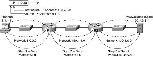 This internetwork uses three different IP network numbers, with one IP network number for each physical network. Simply put, this internetwork does not use subnetting.
For Hannah to send a packet to the web server, a few separate steps happen:
Figure 11-1 shows each of these three steps; the next three sections of this chapter take a closer look at each. Step 1: Leaving Your Neighborhood the Same Way, Every TimeFor most people who have a car, when you leave your house or apartment, you can only drive one direction. Eventually, you'll get to some intersection, where you can make a choice of where to turn. If you know where you're going, you can go ahead and turn. If not, you can look for road signs at each intersection, with the road signs telling you which way to turn. In Figure 11-1, Hannah is in the same basic situation. After Hannah's PC's IP software has built the IP packet that needs to be sent to the server, it needs to know where to send the packet first. As it turns out, because R1 is the only router attached to Hannah's IP network (network 8.0.0.0), she needs to send the packet to R1. To send the packet to R1, Hannah needs to know R1's IP addressspecifically, the IP address of the router interface that's connected to the same Ethernet as Hannah. In TCP/IP terminology, R1 would be Hannah's default router, or default gateway. A PC's default router is simply the router to which that PC sends packets when the destination is in another network or subnet. As you can see in Figure 11-2, Hannah knows her default router is R1. Figure 11-2. By Default, Leave Your Network Via the Default Router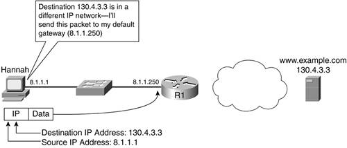 Hannah is in IP network 8.0.0.0, and R1 is the only router that's connected to that IP network. Because Hannah knows that routers know how to route packets, it makes sense that Hannah should forward the packet to R1. However, there are several little details that are important to note in Figure 11-2. First, Hannah's PC knows its default router by the IP address, not by the name. Routers typically have one IP address per physical interface; Hannah needs to know R1's IP address on R1's Ethernet1 interface in this case, because R1's Ethernet1 interface is connected to the same Ethernet LAN that Hannah is. (Because routers have lots of interfaces of many different types, routers label the physical interfaces with a name and a number, such as Ethernet1.)
The last details to point out have to do with how the packet gets from Hannah to R1. Notice in Figure 11-2 that Hannah's IP address (8.1.1.1) is listed as the source and www.example.com's IP address (130.4.3.3) is listed as the destination. So, how does Hannah get the packet to R1? Well, there are a few things to cover to get the full story, including encapsulation and a protocol called Address Resolution Protocol (ARP), which you will learn about in the next sections. Getting into Your Car to Drive to LunchWhen it's time to take a lunch break and your office building isn't close to any restaurants, you might have to get in your car and drive. If you're meeting some friends or business associates for lunch, and you talk before meeting them there, you probably don't bother to mention how you'll be driving to the restaurant. They typically aren't that interested in how you get there. Likewise, before an IP packet can do the equivalent of driving over the roads, it needs to do the equivalent of getting into a car. Before an IP packet can cross an Ethernet, it has to be encapsulated inside an Ethernet frame. When performing the encapsulation, Hannah happens to overcome two different problems:
The solution to the first problem, as you've probably guessed, is encapsulation. Remember: Each layer in the TCP/IP acrchitecural model provides services to the layer above it. Ethernet sits at the network interface layer of TCP/IP, right below the internetwork layer. To get the packet from Hannah to R1, IP uses Ethernet. Hannah encapsulates the IP packet in an Ethernet frame for transmission over the LAN. Figure 11-3 shows the details. Figure 11-3. Encapsulating an IP Packet in an Ethernet Frame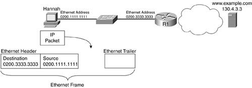 A quick review of Ethernet encapsulation might be helpful. Other layers' protocols add only a header when they encapsulate data. However, data link layer protocolsEthernet includedadd both a header and a trailer, with the IP packet being placed between the header and trailer. The Ethernet header contains several fields, including both the source and destination Ethernet address fields. The trailer contains the frame check sequence (FCS) field, which determines whether errors occurred during physical transmission; if errors did occur, the receiver discards the frame. In Figure 11-3, Hannah's PC takes the following steps to encapsulate and send the IP packet into an Ethernet frame:
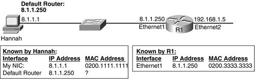
By encapsulating the IP packet in an Ethernet frame, Hannah has created something that can be transmitted across the Ethernet LAN. Now Hannah just has to solve the other problem of making sure that the frame gets to R1 and making sure that R1 processes the frame when it is received. While you're thinking about encapsulation, it's a good idea to review encapsulation at the other layers. All layers of the TCP/IP model use encapsulation, but now you've seen how it works at each layer. For instance, the HTTP protocol defines headers, and when a web browser or web server sends data, HTTP encapsulates the data inside an HTTP header. It's useful to see all the headers in at least one example, as shown in Figure 11-4. This figure shows the Ethernet, IP, TCP, and HTTP headers, along with the end user data (a web page) in the response from the web server. Figure 11-4. Encapsulating an IP Packet in an Ethernet Frame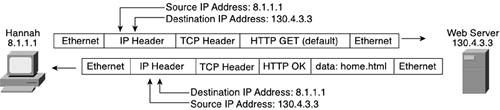 For the rest of this chapter, you'll read about routing and ignore anything after the IP header. However, keep in mind that the whole goal is to deliver application data, as shown in Figure 11-4. The other dilemma that Hannah faces is that she wants to deliver the packet to R1. Not only does the packet need to get to R1, but R1 needs to think that it should process the packet. As you can see in Figure 11-4, Hannah put her own Ethernet address in the frame as the source address, and she put R1's address as the destination. The fact that Hannah included R1's Ethernet address as the destination is the key to solving her second dilemma. As shown in Figure 11-5, when you send a frame whose destination address is 0200.3333.3333, the frame should be delivered to R1. Figure 11-5. Using the Ethernet Frame to Deliver the Packet to the Default Router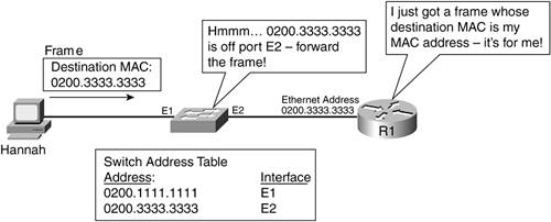 In this figure, the Ethernet switch happens to have already learned its entries for Hannah's (0200.1111.1111) and R1's (0200.3333.3333) Ethernet MAC addresses. With a destination address of 0200.3333.3333, the switch simply looks at the frame and decides to send the frame out its E2 interface. The frame, which, of course, has the IP packet in it, is delivered to R1. Finally, the packet has made it to the default router. The router will know to process the incoming frame because the destination Ethernet address is its own address. Learning How to Go to the Default Post Office (Router)The first time Hannah tries to build the Ethernet header, she will need more information. To finish building the Ethernet header, Hannah needs to put R1's Ethernet address in the header as the destination address. The problem is that Hannah knows the default gateway IP addressin this case 8.1.1.250but she doesn't know R1's Ethernet address on that same interface. A host can learn its default gateway IP address in two ways. In some cases, the default gateway IP address is simply typed into the right place in the PC's configuration. In other cases, the host learns the default gateway IP address dynamically, using the Dynamic Host Configuration Protocol (DHCP). IP hosts use DHCP to automatically discover their own IP address, as well as the IP address of their default router. To keep the coverage focused on the basics, this chapter doesn't cover the details of how DHCP works. Regardless of how Hannah knows her default gateway IP address, she must know it. In contrast, a host does not knowat least ahead of timethe MAC address used to reach the default router (0200.3333.3333 in this example). To learn the MAC address information, Hannah uses ARP. ARP is a TCP/IP protocol that can specifically help solve the problem of knowing an IP address and needing to know the corresponding LAN MAC address. To see how ARP works, examine Figure 11-6, which shows what Hannah and R1 know before Hannah uses ARP. Figure 11-6. What Hannah and R1 Know Before Using ARP
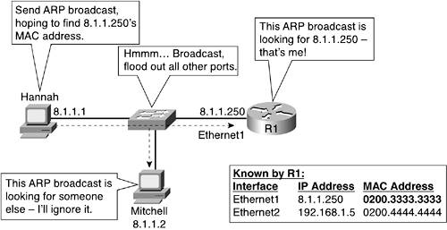
For Hannah to learn what R1's Ethernet MAC address is, she just needs to ask R1. Hannah does so by sending an ARP broadcast. An ARP broadcast is a message that simply says, "Hey, if this is your IP address, tell me your Ethernet MAC address." It's called a broadcast because the destination MAC address of the ARP broadcast is the Ethernet broadcast address of FFFF.FFFF.FFFF. Because switches forward LAN broadcasts to all devices in the network, everyone on the LAN gets the ARP broadcast. Each IP host on the LAN examines the ARP broadcast, but only R1 has IP address 8.1.1.250 configured, so it is the only one that should reply. Figure 11-7 shows the basic process. Figure 11-7. Hannah Sending an ARP Broadcast, Looking for 8.1.1.250's Ethernet Address
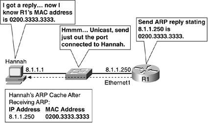
In Figure 11-7, all other IP hosts on the LAN receive the ARP broadcast because the switch floods the frame out all physical interfaces except the port connected to Hannah. Because everyone in network 8.0.0.0 should be somewhere on this Ethernet, if IP address 8.1.1.250 exists, then that device should get the ARP request. The ARP broadcast lists the IP address for which it is searching for the corresponding MAC address. Therefore, Mitchell ignores the request, and R1 decides to reply. R1 replies with an ARP message called an ARP reply. Note that the ARP reply does not use a broadcast destination Ethernet address; instead, the destination address of the sender of the ARP broadcast is used. In this case, the destination is Hannah's Ethernet address (0200.1111.1111). As a result, the LAN switch does not flood the frame holding the ARP reply out all ports; instead, it forwards the frame only to Hannah. Figure 11-8 shows the ARP reply. Figure 11-8. ARP Reply from R1 to Hannah
Inside the data portion of the packet, the ARP reply contains the original IP address (8.1.1.250) and the corresponding MAC address (0200.3333.3333). Finally, Hannah knows the Ethernet MAC address that corresponds to the default gateway IP address. Hannah puts the information in a place called the ARP cache, so that the next time she needs to send a packet to the default gateway, she does not need to send another ARP broadcast. An ARP cache is nothing more than a place in memory in an IP host where IP addresses and their corresponding MAC addresses are recorded. Summary of Step 1Although it took about 10 pages of this chapter, the first step in this simple routing example boils down to a pretty basic process, as follows:
Although this short routing algorithm doesn't match every possibility, it certainly matches the logic Hannah uses to try to send a packet to the web server at 130.4.3.3. Toward the end of this chapter, you'll learn a few exceptions to how an IP host might behave, but for now, Hannah's part of this example is complete. The next section discusses what R1 does with the packet. Step 2: Choosing Which Road to Take at the First IntersectionWhen you drive from your house in your car, you typically leave your neighborhood going the same general direction until you get to an intersection. Of course, you know how to get where you are going, so you don't need to look at the road signs to choose which way to turn. However, someone who's been visiting you might not know the local roads. When the visitor get to the intersection, he can look at the road signs to decide where to drive. Comparing networks to roadways, routers are like an intersection; however, the router makes the choice of where to send a packet, rather than a driver choosing where to turn. When a packet arrives at a router, the router looks at the equivalent of a road signsomething called a routing table in networking. The router looks at where the packet wants to go (the destination IP address) as well as at the routing table. By comparing the two, the router can choose where to send the packet next. The same internetwork is used for the examples throughout this chapter. At this point in the example, an Ethernet frame is arriving on R1's left-side (Ethernet1) interface. The frame contains the IP packet, sent by Hannah (8.1.1.1), with the destination address being the www.example.com web server (130.4.3.3). Figure 11-9 depicts this point in the process. Figure 11-9. The Beginning of R1's Routing Logic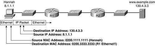 At this point in the process of routing the packet to the web server, the frame is just entering R1. R1 needs to forward the packet to R2 next. The process that R1 uses to forward the packet can be broken down into three steps:
The next sections cover each topic in sequence. The Useful but Short Life of an Ethernet FrameAfter receiving the frame that Hannah sent, the first steps in R1's logic can be summarized as follows:
The FCS field in the Ethernet trailer is the field that lets an Ethernet NIC find out if the frame experienced errors. If the frame is error free, R1 removes the Ethernet header and trailer. In Figure 11-9, after R1 checks the FCS and finds out the frame has not had errors, R1 removes the Ethernet header and trailer. R1 is left with an IP packet, whose source IP address is 8.1.1.1 (Hannah), and whose destination is 130.4.3.3 (web server). Deciding Where to Go NextRouters perform routing by looking at the destination IP address of the IP packet. The term routing refers to the process by which a router examines a recently received packet, looks at the destination IP address, and makes a decision about where to forward the packet next. For routing to work well, the router needs to know how to reach the various IP networks and subnets in the internetwork. Routers choose where to forward packets by looking at a routing table. The key to understanding the process of routing revolves around the IP routing table. The IP routing table includes a list of IP network or subnet numbers, along with instructions on how this router should forward packets in order to deliver the packets to that network or subnet. Whew, that's a long definition, but the concept is simple, particularly with an example. Figure 11-10 shows R1's routing table. Figure 11-10. Routing Decisions Based on the Routing Table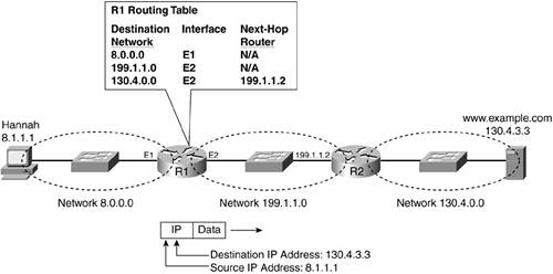 Before the packet arrives at R1, R1 will have built the routing table with the expectation that it will need to know this information one day. In the internetwork used for the example in this chapter, there are three IP networks, so R1's routing table lists three IP networks. Each line in the routing table lists the IP network, along with the routing instructions for this router. These instructions tell R1 how to forward packets so that they will reach each network. When R1 receives the Ethernet frame from Hannah, it first checks for errors. If there are no errors, R1 discards the Ethernet header and trailer and is left with the original IP packet. That IP packet is listed underneath R1 in Figure 11-10. From that point, the process of routing works as follows:
For instance, notice the routing table entry for network 130.4.0.0. You know from Chapter 10 that network 130.4.0.0 includes all IP addresses between 130.4.0.1 through 130.4.255.254, inclusive. Of course, the web server's IP address, 130.4.3.3, is in that range, so the packet matches that entry in the routing table. The last two columns of the routing table tell R1 what to do with packets so that they are delivered successfully to the right destinations. From Figure 11-10, it's pretty obvious that R1 should forward the packet out its Ethernet2 interface, so that R2 gets the packet next. In this case, notice that the routing table entry for network 130.4.0.0 lists Ethernet2 as the outgoing interface. It also references R2's IP address as the next-hop router. The next-hop router is simply the next router that needs to receive the packet so that the packet will be delivered correctly. The outgoing interface is the interface on this router out which the packet should be forwarded next. In short, a router receives a packet, matches its routing table, and decides to forward that packet based on the instructions in the routing table. That process is typically called "routing," and it is sometimes called a forwarding decision. However, R1 is not yet finished. Now let's move on to R1's last step for this packet. Yet Another Ethernet Data Link FrameYou can almost feel the excitement in the air. R1 has received the frame, discarded the Ethernet header and trailer, and made a routing decision. However, R1 has an IP packet sitting in memory, and R1 knows it can't simply send an IP packet out its Ethernet2 interface. The solution is simple, and hopefully a little familiar: R1 needs to encapsulate the packet in another Ethernet frame. Until R1 transmits the bits out its Ethernet2 interface, R1's logic is just like Hannah's logic was earlier. R1's logic goes something like this, in this example:
Imagine that R1 doesn't know R2's MAC address. Figure 11-11 shows the ARP broadcast, the ARP reply, and finally, the new Ethernet frame, which delivers the packet from R1 to R2. Figure 11-11. R1's ARP Broadcast, R2's Reply, and Finally Packet Forwarding The process shown in the figure is as follows:
By the way, R1 keeps an ARP cache as well, so it knows that 199.1.1.2's MAC address is 0200.4444.4444. The next time R1 needs to forward a packet to R2, R1 will not have to ARP. Also, notice that this new Ethernet frame is not the same frame that Hannah created and sent; the new Ethernet frame has a new source and destination addresses. However, the IP packet inside the frame is mostly unchanged. Because the IP packet is the entity that makes it through the network without being changed, many people say that routers and routing forward packets end to end through a network. That's because the word "packet" refers to the IP header and data and does not include the data link header and trailer. Summary of Step 2The routing logic that R1 uses can be summarized as follows:
Step 3: Choosing Which Road to Take at the Final IntersectionIn the sample internetwork for this chapter, only two routers exist. Now that the packet, encapsulated in an Ethernet frame, is crossing the Ethernet between R1 and R2, only one more router needs to process the packetnamely, R2. If many more routers existed between Hannah and the web server, they would use logic similar to R1 in the previous section. However, after you get to the final router, the logic changes slightly. To finish this example and to end the discussion of routing, this section covers the same three steps as those for R1 but instead focuses on the differences. The Still Useful, but Still Short Life of an Ethernet FrameEarlier, R1 began its logic when it received an Ethernet frame that was addressed to itself. Likewise, R2 begins its logic the same way. In this case, R2 receives the frame that R1 sent to R2's Ethernet address, with the frame containing the original packet Hannah sent to the web server. This first step in R2's logic matches R1's:
In the sample internetwork, after R2 receives a frame, it is left with the same IP packet, whose source IP address is 8.1.1.1 (Hannah), and whose destination is 130.4.3.3 (web server). The Routing Table at R2: Same Destination, Different Forwarding InstructionsLike R1 before it, R2 next looks at the destination address of the packet, and it compares the address to the routing table. Like R1, R2 should match an entry in the table, and that entry tells R2 what to do with the packet. However, R2's routing table differs from R1's because R2's routing table includes instructions about how R2 should forward IP packets. It's like taking a trip where you turn left at one intersection and right at another. The turn you make depends on where you are. Likewise, the instructions about which interface out which to forward a packet depends on where the router is in the internetwork. Figure 11-12 shows R1's and R2's routing tables to illustrate how R2 behaves differently from R1. Figure 11-12. R2's Routing TableSame Destinations, Different Instructions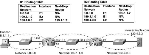 Like R1, to route the packet, R2 needs to compare the destination IP address of the packet to the list of destinations in the routing table. Also like R1, R2 matches its entry for network 130.4.0.0 because the destination, 130.4.3.3, is part of that network. The difference between how R1 and R2 behave relates to the fact that unlike R1, R2's matched routing table entry does not list a next-hop router. From Figure 11-12, you can see that R2 does not need to send the packet to another router, but it should instead send the packet directly to the web server. R2 knows that there's not another router because no next-hop router is listed in the matched routing table entry. R2 simply needs to send the packet directly to the web server at IP address 130.4.3.3. Yet Another Short-Lived Ethernet FrameJust like Hannah and R1 before it, R2 needs to send an IP packet across an Ethernet. It knows the source and destination IP addresses in the packet because those haven't changed during this whole process. R2 knows its own Ethernet address on the outgoing interface. All R2 needs to know is the MAC address that corresponds to the web server so it can finish building the Ethernet frame and send the frame to the web server. To find the web server's Ethernet MAC address, R2 uses the same ARP protocol messages as did Hannah and R1. R2 sends an ARP broadcast, looking for the Ethernet address of host 130.4.3.3 (web server). After the web server replies with an ARP reply, R2 can finish building the Ethernet frame and forward it. After R2 transmits the frame, the LAN switch forwards it so that the web server receives the frame. Finally, the web server has the frame and extracts the packet. The routing of the packet is complete! |
EAN: 2147483647
Pages: 173