Routers and WANs: Still a Match Made in Heaven
| In Chapter 14, you learned some of the details of PPP and HDLC in the context of routers and routing, because these days, most of the devices on the ends of leased lines are routers. Similarly, most of the devices on the ends of Frame Relay PVCs are routers, so it helps to discuss routing briefly with Frame Relay in the picture. To hit the highlights, look at Figure 15-8, with IP addresses shown, three sites, and Frame Relay used for WAN connectivity. Figure 15-8. Routing over PVCs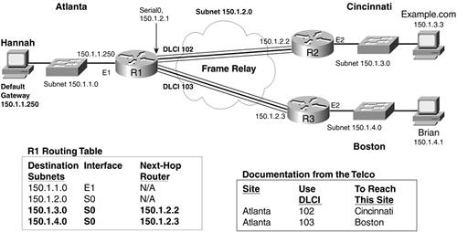 This internetwork uses three routers at three sites. Each has an access link to a local CO, and there's no PVC between R2 and R3, making the network a partial mesh of PVCs. The Frame Relay provider supplied some information to this company when it installed the Frame Relay service, as shown in the legend on the bottom right in the figure. The telco told the customer to configure R1 so that it uses DLCI 102 to send frames to R2, and DLCI 103 to send frames to R3. For this internetwork to work correctly, each of the three routers needs an IP address for its serial interfaces. Notice that the IP addresses shown next to the routers' serial interfaces are in the same subnetsubnet 150.1.2.0. If you study Frame Relay in more depth than is covered here, you'll learn that there are many options for IP addressing over Frame Relay networks; this is just one option. In this case, just like subnet 150.1.2.0 was used when there was Ethernet between R1 and R2 (Chapter 11, "Knowing Where to Turn at Each Intersection [Router]), and just like subnet 150.1.2.0 was used on the WAN link between R1 and R2 (Chapter 14), this example uses that same subnet between R1 and R2. Now that you have an established internetwork to refer to, the next sections review Frame Relay encapsulation and DLCIs and then close with a discussion of Frame Relay Inverse Address Resolution Protocol (ARP). You Can't Just Send DataYou Have to Send a Frame Relay FrameIn this example, Hannah will be opening a browser to connect to the www.example.com website. After using DNS to discover that www.example.com's IP address is 150.1.3.3, Hannah sends a packet to 150.1.3.3. Because 150.1.3.3 is in a different subnet, Hannah's PC sends the packet to her default gatewaynamely, R1. When R1 receives the Ethernet frame, it checks to see if errors occurred. If no errors occurred, R1 extracts the IP packet and begins the process of making a routing decision. Figure 15-9 picks up the routing process at this point. R1 has the packet with destination address 150.1.3.3. That destination address matches the route for subnet 150.1.3.0, which lists outgoing interface Serial0, and next-hop IP address 150.1.2.2, which is R2's IP address on its serial0 interface. Figure 15-9. Forwarding an IP Packet over a Frame Relay PVC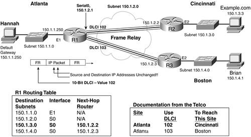 R1 needs to send the packet to R2, physically using its serial0 interface, and logically using the PVC with DLCI 102. First, R1 has to perform Frame Relay encapsulation like the other data link protocols covered in this book by putting the IP packet between a Frame Relay header and trailer. As usual, the trailer has a frame check sequence (FCS) field that allows the receiver of the frameR2 in this caseto know if the frame experienced errors. And, as was mentioned before, the Frame Relay header holds the 10-bit-long DLCI field that identifies the PVC. By putting the right DLCI into the Frame Relay header (102 in this case), the Frame Relay switches inside the telco can forward the frame correctly to R2. Addressing Is Much More Interesting on Frame Relay Than on Serial LinksThe last big concept I'll cover for Frame Relay relates to a dilemma that should be familiar because it happens with Ethernet as well. When R1 needs to build the Frame Relay header, it must put something in the DLCI field102 in this most recent example. You know that R1 should use DLCI 102 because that's what the telco told you would work. The router, however, doesn't have a copy of the documentation from the Frame Relay provider, so it needs more help. To see why, take a close look at the routing table entry for subnet 150.1.3.0 in Figure 15-8. Note that it lists next-hop router of 150.1.2.2, which is R2's IP address, and outgoing interface S0. It does not list which DLCI to use to get to 150.1.2.2. R1 knows the outgoing interface and the next-hop IP address, but it doesn't know which DLCI to use. If there were an Ethernet between R1 and R2, and R1 was faced with this same dilemma, R1 would use IP ARP. R1 would send an IP ARP broadcast that listed the next-hop IP address (150.1.2.2), expecting that R2 would hear the broadcast and send an ARP reply. The reply would include R2's Ethernet MAC address. Frame Relay solves the same problem, but in a different way. As soon as the PVC starts working, R2 announces its IP address to R1, using the VC between the two routers. R1 also announces its IP address to R2, using that same VC. By doing so, both routers learn the other router's IP address that is used on that VC. The message used to announce the IP address and DLCI is called an Inverse ARP message. An Inverse ARP is like an ARP, in that it helps you correlate an IP address to a data link address, but it's different in terms of how the process works. To distinguish between the two, the Frame Relay version uses the word "inverse" in the name. |
EAN: 2147483647
Pages: 173