3.2 Design for Integration
As we mentioned in Section 1.3, a key issue in SOC design is integration of silicon IPs (cores). Integration of IPs directly affects the complexity of SOC designs and also influences verification of the SOC. Verification becomes faster and easier if the SOC interconnect is simple and unified, as was the solution introduced in Chapter 1 for system integration (i.e., use an on-chip communication system or intelligent on-chip bus).
In general, there is no standard for OCBs; they are chosen almost exclusively by the specific application for which they will be used and by the designer's preference. Two main types of OCBs and their characteristics are shown in Table 3.1
Table 3.1. OCBs and Their Characteristics
| OCB | Speed | Bandwidth | Arbitration | Example |
|---|---|---|---|---|
| System | High | High | Complex | ARM AHB |
| Peripheral | Low | Low | Simple | PCI Bus |
A detailed discussion on design of buses and their architectures is beyond the scope of this book. Here, we are mainly interested in using an OCB for system integration.
A typical SOC uses both system and peripheral OCBs. There are also a lot of other wires, such as dedicated links and control signals, between blocks. This is shown in chapter 1, Figure 1.5.
More on VoIP SOC
Figure 1.1 showed the block diagram of a gateway VoIP SOC. We also defined its subsystems. Let's examine this SOC more carefully and see how we can use an intelligent OCB for this VoIP SOC. A gateway VoIP SOC is a device that is used for carrier VoIP gateway functions such as vocoders, echo cancellation, data/fax modems, and VoIP protocols. Currently, there are a number of these devices available from several vendors and, typically, these devices differ from each other depending on the type of functions and voice processing algorithms they support.
Bridging of traditional circuit-switched voice to packet-switched networks is handled by mediation gateways. These are usually proprietary box designs with specialized backplanes . These systems include a chassis and a variety of optional interfaces that can be configured based on customer requirements. Voice processing takes place on a voice-processing subsystem, which is a PCB, attached to the system backplane.
In order to reduce the size of these subsystems, SOCs are used in such systems to provide voice-processing and packet-processing functions to bridge between traditional TDM data and the emerging IP/ATM transport backbone.
Table 3.2 shows some of the key features and their requirements for a mediation gateway SOC voice processor.
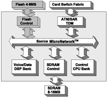
Figure 3.1 shows a VoIP SOC architecture using SiliconBackplane. Here, we have multiple-processor cores (CPU is used for packet protocols and overall control function), multi-DSP cores (DSP is used for voice and modem protocols and LEC), SDRAM (serves all the cores), and I/Os (flash control for card boot up and TDM controller) all unified by SiliconBackplane.
Figure 3.1. VoIP SOC Architecture Using SiliconBackplane (Copyright 2002, Sonics, Inc.)

Table 3.2. Mediation Gateway SOC Voice Processor Feature and Requirement Summary
| Feature | Requirement |
|---|---|
| CODECS | G.711, G.729, G.726 |
| Transport/Packet | AAL1, AAL2, UDP, TCP, IP, TDM |
| Stream I/O | H.100/H.110, TSI, Utopia, Ethernet |
| Host I/O | PCI/Synch Proprietary |
| Other | Memory : 816MB, SDRAM, 32 BIT Flash : 4 8 MB Flash/ROM |
| SOC Interconnect | Proprietary |
| Tone Processing | DTMF, MF |
| Line Echo Canceller (LEC) | G.168 Compliant |
A typical voice-to-packet flow consists of the following steps:
-
Voice port receives voice or fax.
-
Voice port writes frames to memory.
-
Each packet processor reads data, processes data, and then writes data back into memory for the next processor.
-
Packet port reads packets from memory.
-
Packet port sends packets out onto packet network.
-
CPU controls all the above transfers.
And a packet-to-voice flow includes the following steps:
-
Packet port receives packets from packet network.
-
Packet port writes packets to memory.
-
Each packet processor reads data, processes data, and then writes data back into memory for the next processor.
-
Voice port reads frames from memory.
-
Voice port sends voice or fax out onto voice/fax interface.
-
CPU controls all the above transfers.
In this design we can go up to 4GB/s SiliconBackplane BW (128bits, 250MHz).
Some of the benefits of using SiliconBackplane in a VoIP SOC are as follows :
-
Fast and early architectural prototyping. This decreases design-cycle times, promotes early optimization, increases confidence, and improves verification time.
-
High reusability of cores. This will improve your TTM.
-
Late-stage architectural trade-offs and ECOs. You can insert additional functional units into the SOC architecture plug-and-play. For example, you can reduce or increase processing power by inserting a new CPU into the architecture.
-
High performance. You can increase the number of channels to 1000 and beyond.
-
Flexibility. You can scale down to small, low-cost, point solutions.
| |
| Top |
EAN: 2147483647
Pages: 61