Drawing Shapes
Were you one of those kids who, way back in school, passed away the boring hours of algebra class by doodling in the margins of the book? If so, you're in luck. Now that you're a grown up and you're learning Java programming, you don't have to doodle in the book. Instead, you can write programs that doodle on-screen.
This chapter is a gentle introduction to the fascinating world of drawing in Java. The designers of Java call this feature Java 2D. With Java 2D, you can draw basic shapes such as lines, arcs, rectangles, ellipses, and so on. You can set the style used to draw the shape's outline, and you can fill the shape with a solid color, a gradient fill, or text that's created from an image. You can make your shapes solid or transparent, and you can rotate, clip, skew, and do all sorts of other unspeakable things to them.
Getting a Graphics Context
Before you can do any drawing with Java 2D, you have to get yourself an object called a graphics context. The best way to do that is to place all the code that does your drawing in the paint method of a component that's added to a frame or panel so it can be displayed. The paint method receives the graphics context for the component as a parameter.
The paint method is called by Swing whenever a component needs to be repainted for any reason. That happens when the component is first displayed, but it can happen again if the user minimizes the window that displays the component and then restores it-or if the user moves another window over it and then moves that window out of the way. In addition, you can cause the paint method to be called at any time by calling the component's repaint method. You should do this whenever something happens that affects the appearance of the component.
The graphics context object is created from a class called Graphics2D. However, just to be ornery, the paint method is passed an object of the Graphics class, from which Graphics2D is derived. As a result, the very first thing you need to do in your paint method is to cast the Graphics parameter to a Graphics2D object, like this:
public void paint(Graphics g)
{
 Graphics2D g2 = (Graphics2D)g;

 // more to come...
}
| Tip |
The Graphics2D class has a setRenderingHint method that lets you set a variety of hints that influence how your drawings are rendered to the component. Most of them are pretty esoteric, but one can give you dramatically better-looking graphics: the antialiasing hint. To apply it, use this statement: g2.setRenderingHint( RenderingHints.KEY_ANTIALIASING, RenderingHints.VALUE_ANTIALIAS_ON); |
To draw a shape, you must first create a Shape object that represents the shape you want to draw. Java 2D provides several different classes that implement the Shape interface. I have more to say about those classes later in this chapter, but to get started, I create a basic rectangle:
Shape rect = new Rectangle2D.Float(10, 20, 120, 150);
This statement creates a rectangle whose upper-left corner is at (10, 20), whose width is 120, and whose height is 150. Note that the upper-left corner of a component is (0, 0), so this rectangle appears in the upper-left part of the component's display area.
| TECHNICAL STAUFF |
Never mind about the strange incantation Rectangle2D.Float. I explain that in the section "Creating Shapes" later in this chapter. |
After you have a shape in hand, you can draw it by calling the draw method of the graphics context, like this:
g2.draw(rect);
This method draws an outline of the shape using the current color.
Here are some ways you can tweak a shape:
- Change the color before you draw the shape: Call the setColor method, like this:
g2.setColor(Color.RED);
Here the color is changed to RED.
- Change the thickness of the line used to draw the shape: Call setStroke and pass it a new instance of the BasicStroke class. For example:
g2.setStroke(new BasicStroke(4));
Here the stroke thickness is set to 4.
- Fill a shape with color: Call the fill method. For example:
g2.fill(rect);
- Create a shape with both an outline and a fill color: Call both draw and fill and change the color in between. For example:
g2.setColor(Color.BLACK); g2.draw(rect); g2.setColor(Color.MAGENTA); g2.fill(rect);
Here the rectangle is drawn with a black outline and then filled with magenta.
To give you an idea of how graphics programs are usually constructed, Listing 2-1 shows a simple program that displays an ellipse. Figure 2-1 shows the frame displayed by this program. It's not very exciting, but I promise things get more interesting by the end of this chapter.
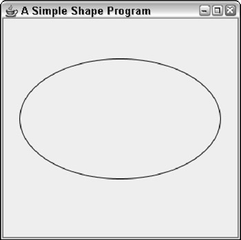
Figure 2-1: The frame displayed by the program in Listing 2-1.
Listing 2-1: The SimpleShape Program
import javax.swing.*; → 1
import java.awt.*;
import java.awt.geom.*;
public class SimpleShape extends JFrame → 5
{
public static void main(String [] args) → 7
{
new SimpleShape();
}
public SimpleShape() → 12
{
this.setSize(300, 300);
this.setTitle("A Simple Shape Program");
this.setDefaultCloseOperation(JFrame.EXIT_ON_CLOSE);
this.add(new PaintSurface(), BorderLayout.CENTER);
this.setVisible(true);
}
private class PaintSurface extends JComponent → 23
{
public void paint(Graphics g) → 25
{
Graphics2D g2 = (Graphics2D)g;
g2.setRenderingHint( → 29
RenderingHints.KEY_ANTIALIASING,
RenderingHints.VALUE_ANTIALIAS_ON);
Shape s = new Ellipse2D.Float( → 33
20, 50, 250, 150);
g2.setPaint(Color.BLACK);
g2.draw(s);
}
}
}
| REMEMBER |
I use the basic structure of this program throughout this chapter to illustrate how graphics programming works. In particular, whenever you see code examples that call methods on an object named g2, you can assume that code appears inside a paint method, such as the one shown in this listing. |
The following paragraphs hit the important points of this program:
|
→ 1 |
The program imports three packages: java.swing, java.awt, and java.geom. Most programs that draw graphics need at least these three classes, and some features may require that you import additional classes. |
|
→ 5 |
The SimpleShape class extends JFrame. However, it works just as well as an applet by extending JApplet instead, provided you remove the constructor statements that call methods that aren't defined by JApplet (in particular, setTitle and setDefaultCloseOperation). |
|
→ 7 |
The main method simply creates a new instance of the SimpleShape class to get things going. |
|
→ 12 |
The SimpleShape constructor does the normal frame housekeeping duties. Then, it adds an instance of the PaintSurface class to the frame just before making the frame visible. |
|
→ 23 |
The PaintSurface class extends JComponent. |
|
→ 25 |
The paint method is overridden here. It receives a single parameter of type Graphics, named g. Notice that the first thing this method does is cast the Graphics parameter to a Graphics2D variable. This parameter allows you to use features of the Graphics2D class that aren't available if the graphics context is treated as a Graphics object. |
|
→ 29 |
After casting the graphics context object, the program sets the rendering hint to use antialiasing. This results in much smoother output. |
|
→ 33 |
After setting the rendering hint, this program creates a shape (an ellipse), sets the painting color to black, and draws the shape on the component. |
Creating Shapes
All the various shapes you can draw with Java 2D are created with classes that implement the Shape interface. Although the Shape interface has some interesting methods of its own, for now I focus on the various classes that implement the Shape interface, listed in Table 2-1.
|
Class Constructor |
Description |
|---|---|
|
Arc2D.Float(float x, float y, float w, float h, float start, float extent, int type) |
Creates an arc, which is a segment of an ellipse defined by the first four parameters. start is the starting angle of the arc in degrees, extent is the angular extent of the arc, and type is the type of arc to draw. Type can be OPEN, CHORD, and PIE. |
|
Ellipse2D.Float(float x, float y, float w, float h) |
Creates an ellipse that fits within the rectangle whose top-left corner is at (x, y), whose width is w, and whose height is h. To create a circle, specify the same value for w and h. |
|
Line2D.Float(float x1, float y1, float x2, float y2) |
Creates a line from (x1, y1) to (x2, y2). |
|
Line2D.Float(Point2D p1, Point2D p2) |
Creates a line from p1 to p2. |
|
Rectangle2D.Float(float x, float y, float w, float h) |
Creates a rectangle whose top-left corner is at (x, y), whose width is w, and whose height is h. |
|
RoundRectangle2D.Float (float x, float y, float w, float h, float arcw, float arch) |
Creates a rounded rectangle whose top-left corner is at (x, y), whose width is w, and whose height is h. The arcw and arch parameters specify the width and height of the corner arcs. |
| TECHNICAL STAUFF |
One complication you'll immediately notice about using these classes is that the class names are weird. For example, the class for creating a rectangle is Rectangle2D.Float. Here's why: The Float class is actually an inner class of the Rectangle2D class, which is abstract. What's not shown in the table is that each of these classes also has an inner class named Double that lets you represent shapes with more precision. For most purposes, float precision is adequate, but you may need to use the Double classes if you're working on an application that requires high precision to represent shapes. |
Figure 2-2 shows several of these shapes drawn in a frame. The code that created this figure is shown in Listing 2-2, later in the chapter. Before examining the code in detail, however, I describe how you use each of the constructors listed in Table 2-1 to create these shapes.
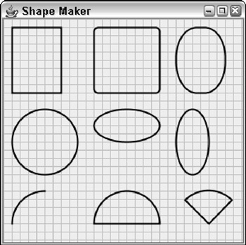
Figure 2-2: A bunch of shapes.
Creating lines
The most basic type of shape is a line, created with the Line2D.Float class. To create a line, you specify the x and y coordinates of the start and end of the line. For example:
Shape line1 = new Line2D.Float(0, 0, 100, 200);
Here a line that goes from (0,0) to (100, 200) is created.
The Line2D.Float class has an alternate constructor that accepts Point2D objects for its parameters. Point2D is also an abstract class with inner classes named Float and Double, so you must use Point2D. Float or Point2D.Double to actually create a Point2D object. For example, here's the same line created using Point2D objects:
Point2D start = new Point2D.Float(0, 0); Point2D end = new Point2D.Float (100, 200); Shape line1 = new Line2D.Float(start, end);
The grid lines in Figure 2-2 were drawn by line shapes inside for loops, like this:
for (int i = 0; i < getSize().width; i += 10) g2.draw(new Line2D.Float(i, 0, i, getSize().height)); for (int i = 0; i < getSize().height; i += 10) g2.draw(new Line2D.Float(0, i, getSize().width, i));
The first for loop draws the vertical lines, and the second draws the horizontal lines.
Creating rectangles
A rectangle requires an (x, y) starting point and a width and height. For example, here's the code that creates the first rectangle shown in Figure 2-2:
Shape rect1 = new Rectangle2D.Float(10, 10, 60, 80);
Here, the rectangle starts at (10, 10). Its width is 60, and its height is 80.
Java 2D also provides a RoundRectangle2D class that lets you create rectangles with rounded corners. The constructor for this class takes two additional parameters that specify the width and height of the arc used to draw the corners. For example, here's the rounded rectangle in the middle of the first row of shapes in Figure 2-2:
Shape round1 = new RoundRectangle2D.Float( 110, 10, 80, 80, 10, 10);
Here the corners are rounded with an arc whose height and width are both 10.
You can create some interesting shapes by using unequal values for the arc's width and height. For example, here's the code for the third shape in the first row of Figure 2-2:
Shape round2 = new RoundRectangle2D.Float(210, 10, 60, 80, 50, 75);
Here the arc's width is 50, and its height is 75.
Creating ellipses
An ellipse is a round shape that fits within a rectangular area. Thus the constructor for the Ellipse2D.Float class is similar to the Rectangle2D. Float constructor. Here's an example that creates an ellipse where the bounding rectangle is a square:
Shape ellipse1 = new Ellipse2D.Float(10, 110, 80, 80);
Note that if the bounding rectangle happens to be a square, the ellipse is a circle. This one is the first shape in the second row in Figure 2-2. Here's the code for the second ellipse in the figure:
Shape ellipse2 = new Ellipse2D.Float(110, 110, 80, 40);
Here the ellipse fits inside a rectangle whose width is 80 and height is 40. Thus the ellipse is short and wide, kind of like me. If I ate a little less and exercised a little more, maybe I'd look more like the third ellipse, created with this code:
Shape ellipse3 = new Ellipse2D.Float(210, 110, 40, 80);
Creating arcs
Another useful type of shape is an arc, which is a segment of an ellipse. To create an arc, you supply the bounding rectangle that contains the ellipse. Here are the parameters you need to specify:
- The starting angle for the arc in degrees-0 is due east, or 3 o'clock as they say in the movies.
- The extent, which is an angle that represents how much of the ellipse the arc spans. This too is specified in degrees. The important thing to know is that the arc travels counterclockwise from the starting point. So if you specify 0 as the starting point and 90 as the extent, the arc travels from 3 o'clock to 12 o'clock high.
- One of three arc types: Arc2D.OPEN indicates that you want to draw just the arc itself. Arc2D.CHORD means you want to draw the arc, and then connect the ends with a straight line to create a closed shape. Arc2D.PIE means you want to use straight lines to connect the ends back to the center of the ellipse, to create a shape that looks like a piece of pie.
Here's an example that creates the first arc shown in the figure:
Shape arc1 = new Arc2D.Float(10, 210, 80, 80, 90, 90, Arc2D.OPEN);
The second arc is created with this statement:
Shape arc1 = new Arc2D.Float(110, 210, 80, 80, 0, 180, Arc2D.CHORD);
And the third arc (the pie slice) is created by this statement:
Shape arc1 = new Arc2D.Float(210, 210, 45, 180, 45, 90, Arc2D.PIE);
Looking at the ShapeMaker program
Now that you've seen how to create a variety of shapes, you're ready to take a glance at Listing 2-2, which draws the shapes that were shown earlier in Figure 2-2. This program relies on a very useful technique for any program that works with more than a few shapes. Instead of creating and drawing each shape separately in the paint method, the shapes are stored in an ArrayList object of type Shape. The shapes are created in the PaintComponent constructor, so the code that creates the shapes is executed only once. Then, in the paint method, an enhanced for loop is used to draw each shape in the ArrayList. This technique is especially handy for programs that let the user draw shapes. Each time the user draws a new shape, you just add the shape to the ArrayList. Then, whenever the paint method is called, all the shapes are drawn.
Listing 2-2: The ShapeMaker Program
import javax.swing.*;
import java.awt.event.*;
import java.awt.*;
import java.awt.geom.*;
import java.util.*;
public class ShapeMaker extends JFrame
{
public static void main(String [] args)
{
new ShapeMaker();
}
public ShapeMaker()
{
this.setSize(300, 300);
this.setTitle("Shape Maker");
this.setDefaultCloseOperation(JFrame.EXIT_ON_CLOSE);
this.add(new PaintSurface(), BorderLayout.CENTER);
this.setVisible(true);
}
private class PaintSurface extends JComponent
{
ArrayList shapes = new ArrayList();
Point startDrag, endDrag;
Shape found = null;
public PaintSurface()
{
Shape s;
// a rectangle
s = new Rectangle2D.Float(10, 10, 60, 80);
shapes.add(s);
// a rounded rectangle
s = new RoundRectangle2D.Float(110, 10, 80, 80,10, 10);
shapes.add(s);
// a rounded rectangle
s = new RoundRectangle2D.Float(210, 10, 60, 80, 50, 75);
shapes.add(s);
// a circle
s = new Ellipse2D.Float(10, 110, 80, 80);
shapes.add(s);
// an ellipse
s = new Ellipse2D.Float(110, 110, 80, 40);
shapes.add(s);
// another ellipse
s = new Ellipse2D.Float(210, 110, 40, 80);
shapes.add(s);
// an arc
s = new Arc2D.Float(10, 210, 80, 80, 90, 90, Arc2D.OPEN);
shapes.add(s);
// another arc
s = new Arc2D.Float(110, 210, 80, 80, 0, 180, Arc2D.CHORD);
shapes.add(s);
// another arc
s = new Arc2D.Float(210, 210, 80, 80, 45, 90, Arc2D.PIE);
shapes.add(s);
}
public void paint(Graphics g)
{
Graphics2D g2 = (Graphics2D)g;
// turn on antialiasing
g2.setRenderingHint(
 RenderingHints.KEY_ANTIALIASING,
 RenderingHints.VALUE_ANTIALIAS_ON);
// draw background grid
g2.setPaint(Color.LIGHT_GRAY);
for (int i = 0; i < getSize().width; i += 10)
 g2.draw(new Line2D.Float(i, 0, i, getSize().height));
for (int i = 0; i < getSize().height; i += 10)
 g2.draw(new Line2D.Float(0, i, getSize().width, i));
// draw all the shapes in the array list
g2.setColor(Color.BLACK);
g2.setStroke(new BasicStroke(2));
for (Shape s : shapes)
g2.draw(s);
}
}
}
Filling Shapes
As explained earlier in the chapter, you can fill a shape with a solid color by first calling the setPaint method to set the fill color, and then calling the fill method to fill the shape. For example:
g2.setColor(Color.RED);
g2.fill(rect1);
Here the fill color is set to RED, and then the shape named rect1 is filled.
But there's more to filling than solid colors. In the following sections, you find out how to create fills that are partially transparent and fills that gradually fade from one color to another.
Drawing transparently
Java 2D lets you create transparent shapes by specifying a compositing rule. The compositing rule can do more than just set the transparency, but its other uses are more advanced than this short chapter allows. So (rather than go into all the gory details) let me just ask you to accept my word that to set the transparency, you must use this odd incantation:
g2.setComposite(AlphaComposite.getInstance(
 AlphaComposite.SRC_OVER, 0.50F));
The key here is the float parameter value, which must be from 0.0 to 1.0. In this case, the transparency is set to 0.50F, which means that the shapes are 50 percent transparent. As a result, whatever is under the shape when it is drawn partially shows through.
Using a gradient fill
Instead of using a solid color, you can specify a gradient fill, which blends two colors by using the GradientPaint class, whose constructors are shown in Table 2-2. A gradient fill is created from two color points. Imagine a line drawn between these two points. The gradient fill varies the color smoothly from the color that's set at the first point to the color set at the second point. Then it extends the colors on this line at 90-degree angles to the line to fill an entire area.
|
Constructor |
Description |
|---|---|
|
GradientPaint(float x1, floaty1, Color c1, x1 float x2, float y2, Color c2) |
Creates a gradient in which the color at point x1, y1 is color1, the color at point x2, y2 is color2, and points in between are smoothly blended. All points beyond the x1, y1 point have color1, and all points beyond the x2, y2 point have color2. |
|
GradientPaint(Point2D p1, Color c1, Point2D p2 Color c2) |
Creates a gradient in which the color at point p1 is color1, the color at point p2 is color2, and points in between are smoothly blended. All points beyond p1 have color1, and all points beyond p2 have color2. |
|
GradientPaint(float x1, floaty1, Color c1, float x2, float y2, Color c2, boolean cyclic) |
Same as the first constructor, but if the cyclic parameter is true, the gradient pattern repeats infinitely beyond the two points. |
|
GradientPaint(Point2D p1, Color c1, Point2D p2 Color c2, boolean cyclic) |
Same as the second constructor, but if the cyclic parameter is true, the gradient pattern repeats infinitely beyond the two points. |
Here's an example that sets a gradient fill that varies the color from magenta to yellow:
GradientPaint gp =
 new GradientPaint(0, 0, Color.MAGENTA,
 0, 100, Color.YELLOW);
Here are some suggestions for choosing the location of the two color points:
- The points are relative to the top-left corner of the component, not to the shape you're filling. You usually want both points to lie at or near the edges of the shape you're drawing.
- The easiest way to keep the number straight is to create variables named x, y, width, and height, and use these variables to create both the shapes and the gradient fills.
- If you want to have the first color at the top and the second color at the bottom, use (x, y) for the first point and (x, y+height) as the second point.
- If you want to have the first color at the left and the second color at the right, use (x, y) for the first point and (x+width, y) as the second point.
- Each point is painted with the full color you specify. If you want a band of solid color on the edges of the object before the gradient begins, choose points that are somewhat inside the object. For example, use (10, 10) and (width-10, height-10).
- If you use the third or fourth constructors and specify true for the cyclic parameter, the gradient pattern repeats itself. Then, you want to pick points that are closer together so you can see the repetition within your object. For example, if the width of the object is 150, pick points such as (0, 0) and (0, 50) to see the cycle repeat three times within the object.
Table 2-3 shows four different examples of gradient fills created with the GradientPaint class. Each of the rectangles is 100 x 100. The table also shows the location of the points for each fill relative to x, y, width, and height. For each fill, the color for point 1 is black, and for point 2, white.
|
Gradient Fill |
Name |
Point 1 (Black) |
Point 2 (White) |
|---|---|---|---|
|
|
gp1 |
x, y |
x, y + height- |
|
|
gp2 |
x, y |
x + width, y |
|
|
gp3 |
x, y+35 |
x, y + height + 35- |
|
|
gp4 |
x+35, y+35 |
x+width-35, y+height-35- |


Here's the code that creates these four gradient fills:
GradientPaint gp1 = new GradientPaint(x, y, Color.BLACK,
 x, y + h, Color.WHITE);
GradientPaint gp2 = new GradientPaint(x, y, Color.BLACK,
 x + w, y, Color.WHITE);
GradientPaint gp3 = new GradientPaint(x, y+35,
 Color.BLACK, x, y+h-35, Color.WHITE, true);
GradientPaint gp4 = new GradientPaint(x+35, y+35,
 Color.BLACK, x+w-35, y+h-35, Color.WHITE, true);
Using this code as a starting point, you can devise many different variations to create your own fills.
Rotating and Translating
This section describes two methods of the Graphics2D class that modify how a shape is drawn:
- The translate method moves the (0, 0) point from the top-left corner to any arbitrary point.
- The rotate method rotates the component's coordinate system so that shapes are drawn at an angle.
Translate method
The translate method takes two parameters, namely the x and y coordinates of the point you want to designate as the center of the universe. For many graphics applications, translating to the center of the component is useful, so (0, 0) is in the middle of the component. Then points with a negative x value appear to the left of center, and points with a negative y value appear above center. Here's a code snippet that does that regardless of the size of the component:
int cx = getSize().width / 2; // center X;
int cy = getSize().height / 2; // center Y;
g2.translate(cx, cy);
Rotate method
Rotation is a little more complicated. The rotate method itself is simple enough-it takes just a single parameter that rotates the coordinate system by the angle you specify. Here's an example:
g2.rotate(angle);
| TECHNICAL STAUFF |
The angle isn't measured in degrees. Instead, it's measured in radians, a unit that (if you'll remember back to your high-school math) is the length of the arc subtended by the angle (assuming the radius is 1). Java's Math class has a handy toRadians method that automatically converts degrees to radians. So, to rotate the coordinate space by 45 degrees, you use this statement: g2.rotate(Math.toRadians(45)); |
Note that the rotate method rotates the entire coordinate space for the component you're painting on, not just a single shape. As a result, to draw a shape rotated around its center, you first translate to the center of the shape you want to rotate, call the rotate method, and then draw the shape. The Graphics2D class provides a convenient version of the rotate method that does that for you automatically. It takes three parameters: the rotation angle and the x and y coordinates of the point around which you want to rotate. For example:
g2.rotate(Math.toRadians(45), 100, 150);
Here the coordinate space is rotated 45 degrees around point 100, 150. (The translation is only temporary; the rotate method restores the previous translation after it does the rotation.)
Here's an example from a paint method that creates an ellipse, and then draws it several times at different rotations:
int x = 50;
int y = 75;
int width = 200;
int height = 100;
Shape r1 = new Ellipse2D.Float(x, y, width, height);
for (int angle = 0; angle <= 360; angle += 45)
{
 g2.rotate(Math.toRadians(angle),
 x + width/2, y + height/2);
 g2.setPaint(Color.YELLOW);
 g2.fill(r1);
 g2.setStroke(new BasicStroke(4));
 g2.setPaint(Color.BLACK);
 g2.draw(r1);
}
Here the rotate method is called inside a for loop that varies the angle from 0 degrees through 360 degrees in 45 degree increments. Assuming the paint method has set antialiasing and 50 percent transparency and has drawn the line grids shown in the previous examples, Figure 2-3 shows how the shapes drawn by these statements appear.
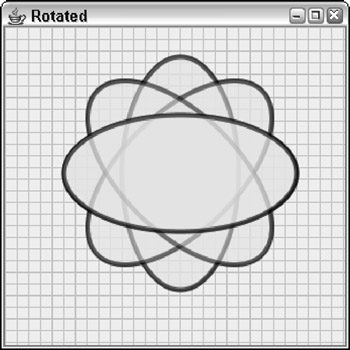
Figure 2-3: Rotated shapes.
Drawing Text
You can use the drawString method to draw the text contained in a string. This method accepts three parameters: the string to be drawn and the x and y coordinates of the lower-left corner of the first character to be drawn (technically speaking, the start of the baseline for the text). Here's an example:
g2.drawString("This is some text!", 100, 50);
Here, the string “This is some text!” is drawn at point (100, 50).
The current stroke, color, translation, and rotation apply to the text that's drawn, as well as the current font that you specify via the setFont method. This method accepts a Font object, like this:
g2.setFont(new Font("Times New Roman", Font.PLAIN, 36));
Here the font is set to 36-point Times New Roman. For more information about creating fonts, refer to Book IX, Chapter 1.
Letting the User Draw on a Component
In many applications, you need to let the user doodle directly on a panel. To do that, you need to create listeners that listen for mouse events such as clicks, drags, or just basic movement. Then you need to coordinate those listeners with the paint method so that the mouse events generated by the user are translated into shapes that are drawn on the component. Table 2-4 lists the mouse events you need to listen for in programs that let the user draw shapes.
Table 2-4: Mouse Events and Listeners
 Open table as spreadsheet
|
MouseListener Method |
Description |
|---|---|
|
void mouseClicked(MouseEvent e) |
The user clicked a mouse button. |
|
void mouseEntered(MouseEvent e) |
The mouse entered a component. |
|
void mouseExited(MouseEvent e) |
The mouse exited a component. |
|
void mousePressed(MouseEvent e) |
The user pressed a mouse button. |
|
void mouseReleased (MouseEvent e) |
The user released a mouse button. |
Open table as spreadsheet
|
MouseMotionListener Methods |
Description |
|---|---|
|
void mouseMoved(MouseEvent e) |
The user moved the mouse without pressing a button. |
|
void mouseDragged(MouseEvent e) |
The user moved the mouse while a button was pressed. |
|
int getButton() |
Gets the mouse button that has been clicked, pressed, or released. The result can be BUTTON1, BUTTON2, BUTTON3, or NOBUTTON. |
|
int getClickCount() |
Gets the number of clicks to determine if the user has double- or triple-clicked. |
|
Point getPoint() |
Gets the mouse position as a Point object. |
|
int getX() |
Gets the x position. |
|
int getY() |
Gets the y position. |
Note that both the MouseListener and MouseMotionListener interfaces have corresponding adapter classes named MouseAdapter and MouseMotionAdapter. If you use one or both of these adapter classes, you only have to override the methods for the events you want to respond to. (For more information about adapter classes and listeners, refer to Book VI, Chapter 2.)
To see how mouse events can be used to create programs that let the user draw on-screen, take a look at a simple program that lets the user draw rectangles. The basic technique used by the program goes something like this:
- When the user presses the mouse button, you make a note of the location to use as the starting point of the rectangle to be drawn.
- When mouse movement is detected, you make a note of the mouse location and call repaint to force the component to be repainted. Then, in the paint method, you draw a temporary rectangle from the original starting position to the current mouse position to give the user a visual clue while he or she is drawing the rectangle. This rectangle is drawn with a light gray line and isn't filled. Each time the user moves the mouse, this rectangle is redrawn according to the current mouse position. As a result, the rectangle appears to grow and shrink with the mouse movements.
- When the user releases the mouse button, you create a new Rectangle2D.Float object using the original starting location and the mouse location when the button was released. You then add the rectangle to an ArrayList of Shape objects and call repaint to force the component to be repainted. This causes all the rectangles in the ArrayList to be drawn in the order in which the user created them.
- Also when the user releases the mouse button, you clear the two mouse locations that were saved while the user was drawing the rectangle. That way, the paint method knows not to draw the temporary rectangle.
Here are a few other points to know about this program before I dive into the code:
- Rectangles created with the Rectangle2D class are always specified with the (x, y) coordinate of the top-left corner and a width and height. However, users don't always draw rectangles starting with the top-left corner. The user might press the mouse button to anchor the rectangle, and then draw the mouse up and to the left, so that the original position is the bottom-right corner instead of the top-left corner. To facilitate this, the program includes a helper method that creates a rectangle from any two arbitrary points that mark opposite corners. This method uses these points to determine the location of the top-left corner and the width and height.
- To make the rectangles visually interesting, the program uses an array of colors to fill each one with a different color. And each rectangle is filled with 50 percent transparency so rectangles beneath it are visible.
- The component surface also shows a grid drawn with Line2D shapes.
Figure 2-4 shows this program in action, after the user has drawn several rectangles. Listing 2-3 provides the complete code for the program.
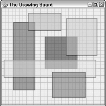
Figure 2-4: The Drawing-Board program in action.
Listing 2-3: The DrawingBoard Program
import javax.swing.*;
import java.awt.event.*;
import java.awt.*;
import java.awt.geom.*;
import java.util.*;

public class DrawingBoard extends JFrame

{

 public static void main(String [] args) → 8
 {
 new DrawingBoard();
 }

 public DrawingBoard() → 13
 {
 this.setSize(300, 300);
 this.setTitle("The Drawing Board");
 this.setDefaultCloseOperation(JFrame.EXIT_ON_CLOSE);
 this.add(new PaintSurface(), BorderLayout.CENTER);
 this.setVisible(true);
 }

 private class PaintSurface extends JComponent
 {
 ArrayList shapes = new ArrayList(); → 24
 Point startDrag, endDrag;

 public PaintSurface()
 {
 this.addMouseListener(new MouseAdapter()
 {
 public void mousePressed(MouseEvent e) → 31
 {
 startDrag = new Point(e.getX(), e.getY());
 endDrag = startDrag;
 repaint();
 }

 public void mouseReleased(MouseEvent e) → 38
 {
 Shape r = makeRectangle(
 startDrag.x, startDrag.y,
 e.getX(), e.getY());
 shapes.add(r);
 startDrag = null;
 endDrag = null;
 repaint();
 }
 } );

 this.addMouseMotionListener(new MouseMotionAdapter()
 {
 public void mouseDragged(MouseEvent e) → 52
 {
 endDrag = new Point(e.getX(), e.getY());
 repaint();
 }
 } );
 }

 public void paint(Graphics g) → 59
 {
 Graphics2D g2 = (Graphics2D)g;

 // turn on antialiasing

 g2.setRenderingHint(
 RenderingHints.KEY_ANTIALIASING,
 RenderingHints.VALUE_ANTIALIAS_ON);

 // draw background grid
 g2.setPaint(Color.LIGHT_GRAY);
 for (int i = 0; i < getSize().width; i += 10)
 {
 Shape line = new Line2D.Float(
 i, 0, i, getSize().height);
 g2.draw(line);
 }

 for (int i = 0; i < getSize().height; i += 10)
 {
 Shape line = new Line2D.Float(
 0, i, getSize().width, i);
 g2.draw(line);
 }

 // draw the shapes
 Color[] colors = {Color.RED, Color.BLUE, → 85
 Color.PINK, Color.YELLOW,
 Color.MAGENTA, Color.CYAN };
 int colorIndex = 0;

 g2.setStroke(new BasicStroke(2)); → 90
 g2.setComposite(AlphaComposite.getInstance(
 AlphaComposite.SRC_OVER, 0.50f));

 for (Shape s : shapes) → 94
 {
 g2.setPaint(Color.BLACK);
 g2.draw(s);
 g2.setPaint(colors[(colorIndex++)%6]);
 g2.fill(s);
 }

 // paint the temporary rectangle
 if (startDrag != null && endDrag != null) → 103
 {
 g2.setPaint(Color.LIGHT_GRAY);
 Shape r = makeRectangle(
 startDrag.x, startDrag.y,
 endDrag.x, endDrag.y);
 g2.draw(r);
 }
 }

 private Rectangle2D.Float makeRectangle( → 113
 int x1, int y1, int x2, int y2)
 {
 int x = Math.min(x1, x2);
 int y = Math.min(y1, y2);
 int width = Math.abs(x1 - x2);
 int height = Math.abs(y1 - y2);
 return new Rectangle2D.Float(
 x, y, width, height);
 }
 }
}
The following paragraphs provide a road map through this program:
|
→ 8 |
The main method creates an instance of the DrawingBoard class. |
|
→ 13 |
The constructor for the DrawingBoard class initializes the frame in the usual way, adding a new instance of a JComponent class named PaintSurface. |
|
→ 24 |
The PaintSurface class begins by defining three instance variables. The first, named shapes, is an ArrayList object that holds the shapes drawn by the user. The next two are Point objects that represent the start and end points for the rectangle currently being drawn by the user. |
|
→ 31 |
The PaintSurface constructor uses anonymous inner classes to create the mouse listeners. The mousePressed method is invoked when the user presses a mouse button. It sets the startDrag and endDrag variables to the current position of the mouse, and then calls repaint to force the component to be repainted. |
|
→ 38 |
The mouseReleased method is called when the user releases the mouse, indicating that a rectangle has been drawn. It calls the makeRectangle method to create a rectangle from the starting x and y values and the current x and y values. Then it adds this rectangle to the shapes collection, clears the startDrag and endDrag points, and calls repaint to force the component to be repainted. |
|
→ 52 |
The mouseDragged method in the MouseMotionAdapter anonymous class is called when the mouse moves while the button is held down. This method simply sets the endDrag variable to the new mouse location and calls repaint to repaint the component. |
|
→ 59 |
The paint method is where the good stuff happens in this program. This begins by casting the Graphics object to a Graphics2D object, turning on antialiasing, and drawing the background grid. Then it draws the shapes from the shapes collection. |
|
→ 85 |
To fill each rectangle with a different color, the program creates an array of Color objects that specifies six different colors. Then, it defines a variable named colorIndex to index the array. Each time a rectangle is drawn, this index is incremented. |
|
→ 90 |
The stroke thickness is set to 2, and the setComposite method is used to set the transparency to 50 percent. |
|
→ 94 |
An enhanced for loop is used to draw each rectangle. First, the color is set to black, and the rectangle is drawn. Then, the color is set, and the rectangle is filled. The modulo division operator (%) is used to constrain the index from 0 through 5, and the index is incremented so the next rectangle uses the next color in the array. |
|
→ 103 |
This if statement draws the temporary rectangle while the user is dragging the mouse. If either startDrag or endDrag is null, the rectangle isn't drawn. |
|
→ 113 |
makeRectangle is a helper method that creates a Rectangle2D.Float object given the points of two opposite corners. It sets the starting point to the smaller of the two x values and the smaller of the two y values, and sets the width and height to the absolute value of the difference between the two x values and the two y values. |
Book I - Java Basics
Book II - Programming Basics
- Book II - Programming Basics
- Java Programming Basics
- Working with Variables and Data Types
- Working with Numbers and Expressions
- Making Choices
- Going Around in Circles (Or, Using Loops)
- Pulling a Switcheroo
- Adding Some Methods to Your Madness
- Handling Exceptions
Book III - Object-Oriented Programming
- Book III - Object-Oriented Programming
- Understanding Object-Oriented Programming
- Making Your Own Classes
- Working with Statics
- Using Subclasses and Inheritance
- Using Abstract Classes and Interfaces
- Using the Object and Class Classes
- Using Inner Classes
- Packaging and Documenting Your Classes
Book IV - Strings, Arrays, and Collections
- Book IV - Strings, Arrays, and Collections
- Working with Strings
- Using Arrays
- Using the ArrayList Class
- Using the LinkedList Class
- Creating Generic Collection Classes
Book V - Programming Techniques
Book VI - Swing
- Book VI - Swing
- Swinging into Swing
- Handling Events
- Getting Input from the User
- Choosing from a List
- Using Layout Managers
Book VII - Web Programming
Book VIII - Files and Databases
- Book VIII - Files and Databases
- Working with Files
- Using File Streams
- Database for $100, Please
- Using JDBC to Connect to a Database
- Working with XML
Book IX - Fun and Games
EAN: 2147483647
Pages: 332
- Article 312 Cabinets, Cutout Boxes, and Meter Socket Enclosures
- Article 360 Flexible Metallic Tubing Type FMT
- Article 500 Hazardous (Classified) Locations, Classes I, II, and III, Divisions 1 and 2
- Tables 11(A) and 11(B)
- Annex C. Conduit and Tubing Fill Tables for Conductors and Fixture Wires of the Same Size
