Routing Concepts
 |
Solaris supports many different kinds of network interfaces, for both local area and wide area transmission. Ethernet and FDDI are commonly used for creating networks of two or more systems at a single site through a LAN, while supporting high-speed, wide area connections through T1 and X.25 lines ”and most recently, ATM (Asynchronous Transfer Mode) networks. A hub is a device that can interconnect many devices so that they can be channeled directly to a router for wide area connection. For example, each physical floor of a building may have a hub, and each of these hubs then connects to a single hub for the whole building. This hub is connected to an Internet service provider (ISP) through a router ( router.company.com ) and a dedicated ISDN service. A general rule of thumb for connecting routable networks is not to have more than three levels of connection between a server and a router; otherwise , the number of errors increases dramatically. Figure 35-1 shows a possible Class C network configuration for this building.
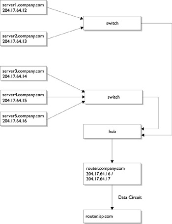
Figure 35-1: Class C network configuration (203.17.64.0).
This configuration is fine if a single company ( company.com ) owns and occupies this building and both use the same ISP. However, let s imagine that company.com downsizes and leases the second floor to a government department, department.gov . The government department wants to make use of the existing ISP arrangements and is happy to share the cost of the ISDN connection. However, they want to logically isolate their network from that of company.com for security purposes ”they intend to install a packet filter on their own router, which explicitly denies or allows packets to cross into the government department s network.
This logical separation can be easily achieved by separating the existing network into two subnets, allowing the government department to install their own router, and then connecting the two networks through that router. Traffic to the ISP can still flow through the existing connection ”even though from the hosts on the second floor, they are now separated from the router. The way that the department s traffic can find the ISP is the kind of problem that routing can solve. More generally , routing allows one host to find a path to any other host on the internet. Figure 35-2 shows the revised configuration for this building, incorporating the changes required by the government department, forming two Class C networks whose routers are connected to each other.
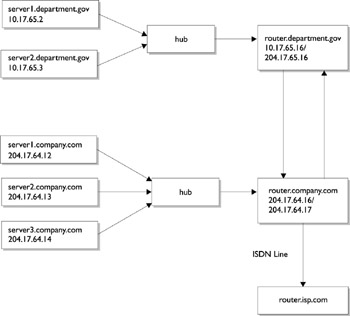
Figure 35-2: Connecting two Class C networks (203.17.64.0 and 203.17.65.0).
It should be clear from these examples that from a network perspective, a host must either be a router or a host. A router can be a Solaris server, which performs other functions (for example, DNS server or NIS server), however, it can also be a dedicated, hardware-based system supplied by another manufacturer (for example, Cisco or Ascend). In this chapter we will examine ways of setting up and configuring a Solaris host to be a router, although it may be that your organization prefers to use a dedicated system for routing.
The basic function of a router, as displayed in Figures 35-1 and 35-2, is to pass information from one network to another. In the examples, information is passed from one Class C network to another, but also to the router of an ISP. The ISP s router then connects with many other ISP s routers, eventually giving global coverage. The information passed between networks is contained in discrete packets, and since the router passes this information along, it follows that the router can potentially make a copy of the data and save it to a local disk. This is the basis of many security- related problems on the Internet, because usernames and passwords are also transmitted as packets and can be intercepted by any intermediate router between client and server.
To be a router, a system must have multiple physical network interfaces. This is distinct from a system having one or more virtual interfaces defined for a single physical interface card. Thus, the router for company.com has the interfaces 204.17.64.16 and 204.17.64.17. The first interface accepts traffic from the internal network and passes it to the second interface, while the second interface accepts traffic from the other routers and passes it to the internal network or to other routers, as appropriate. Having two network interfaces allows data to be passed through the machine and exchanged across different networks. In the previous example, the company.com router was able to exchange information between the department.gov router and the ISP s router. Thus, many routers can be interconnected to form networks in which packets can be passed from a source to a destination host transparently .
Because the department.gov router serves as a packet-filtering firewall, it is likely that the network has a nonroutable, internal structure, which is not directly accessible to the external network but is visible from the router (the 10.17.65.0 network). Thus, a rogue user from company.com will be able to see the external interface for the department.gov router, but will not be able to see the internal interface or any of the hosts beyond, unless he or she manages to break into the router through the external interface. This adds a second layer of protection against intrusion. A packet filter can then be used to explicitly deny connections to machines in the internal network, except for very specific system or network services. For example, a departmental mail server may reside on server1.department.gov , and external machines will ultimately need access to the sendmail ports on this server. This can be achieved by port forwarding, or the ability of the router to map a port on its external interface to a port on a machine on the internal network. For example, a web server on server1.department.gov:80 could be accessed from the external network by connecting to router.department.gov:8080 if the mapping was enabled. These techniques can achieve the necessary logical isolation between external users and actual network configuration, which can be useful for security planning. Packet filtering, port forwarding, and nonroutable networks are discussed later in the chapter.
A machine with more than one network interface may not be configured to act as a router, in which case it is referred to a multihomed host.
| Tip | Multihoming can be useful for performing such functions as load balancing and directly serving different Class C networks, without passing information between them. |
IP Routing
Now that we have discussed how to install, configure, and tune network interfaces, we shall turn our attention to setting up routing and explain how packets are transferred from hosts to routers, and exchanged between routers. We will also examine how to troubleshoot routing problems with traceroute, and introduce the different routing protocols that are currently being used on the Internet.
There are two kinds of routing: static routing and dynamic routing. Static routing is common in simple networks with only a few hosts and networks interconnected. Static routing is much simpler to implement than dynamic routing, which is suitable for large networks where the routes between networks cannot be readily specified. For example, if your organizational network has only two routers connecting three networks, the number of routes that need to be installed statically is four (that is, the square of the number of routers). In contrast, for a building with five routers, the number of routes that need to be specified statically is 25. If a router configuration changes, all of the static configuration files on all of the routers need to be changed (that is, there is no mechanism for the discovery of routes). Alternatively, if a router fails because of a hardware fault, packets may not be able to be correctly routed. Dynamic routing solves all of these problems, but requires more processing overhead on each router.
| Note | There are two related dynamic routing daemons ”in.rdisc, the router discovery daemon, and in.routed, the route daemon ”whose configuration will be discussed at length in this section. |
Overview of Packet Delivery
Before we examine the differences between static and dynamic routing in detail, let s take a step back and consider how information is passed between two systems, whether the exchange is host to host, host to router or router to router. All information is exchanged in the form of discrete packets, which is the smallest unit of information that is transmitted between hosts using TCP/IP. A packet contains both a header and a message component, as shown in Figure 35-3. In order to deliver packets from one host to another host successfully, each packet contains information in the header (which is similar to an envelope) ”among many other fields, it contains the address of the destination machine and the address of the source machine. The message section of the packet contains the actual data to be transferred. Packets are often transferred on the transport layer using the Transmission Control Protocol (TCP), which guarantees the delivery of packets. Some applications use User Datagram Protocol (UDP), where the continuity of a connection cannot be guaranteed . In normal TCP transmission mode, only 64KB of data can be transferred in a single session unless large window support is enabled, in which case up to 1GB of data may be transmitted. The header may also have information inserted by the source machine, which is referred to as data encapsulation.
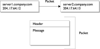
Figure 35-3: A packet has both a message and a header.
| Note | The action of passing a packet is referred to as a hop, so routing involves enabling packets to hop from a source host to any arbitrary host on the Internet. |
In order for packets to be delivered correctly between two hosts, all intermediate routers must be able to determine where the packets have come from, and where they must be delivered. This can be achieved by referring to a host by using its IP address (for example, 203.16.42.58) or it s fully-qualified domain name (for example, server.company.com ). Although it is also possible to refer to a machine by its Ethernet (hardware) address, it is often preferred in TCP/IP to use a logical rather than a physical representation of a machine s network interface card.
Sending a packet across a network makes full use of all network layers . For example, if a telnet session is to be established between two machines, the application protocol specifies how the message and header are to be constructed , information which is then passed to the transport layer protocol. For a telnet session, the transport layer protocol is TCP, which proceeds with encapsulation of the packet s data, which is split into segments. The data is divided based on the size of the TCP window allowed by the system. Each segment has a header and a checksum, which is used by the destination host to determine whether a received packet is likely to be free of corruption. When a segment is due to be transmitted from the source host, a three-way handshake occurs between source and destination: a SYN segment is sent to the destination host requesting a connection, and an acknowledgement (ACK) is returned to the source when the destination host is ready to receive. When the ACK is received by the source host, its receipt is acknowledged back to the destination and transmission proceeds with data being passed to the IP layer, where segments are realized as IP datagrams. IP also adds a header to the segment and passes it to the physical networking layer for transport. A common method of enacting a denial of service attack on a remote host involves sending many SYN requests to a remote host, without completing the three-way handshake. Solaris now limits the maximum number of connections with handshake incomplete to reduce the impact of the problem. When a packet finally arrives at the destination host, it travels through the TCP/IP protocol stack in the reverse order from that which it took on the sender: just like a deck of cards that has been dealt onto a playing table and retrieved from the top of the pack.
The story becomes more complicated when packets need to be passed through several hosts to reach their ultimate destination. Although the method of passing data from source to destination is the same, the next hop along the route needs to be determined somehow. The path that a packet takes across the network depends on the IP address of the destination host as specified in the packet header. If the destination host is on the local network, it can be delivered immediately without intervention of a separate router. For example, a source host 204.12.60.24 on the Class C network 204.12.60.0 can directly pass a packet to a destination 204.12.60.32. However, once a packet needs to be delivered beyond the local network, the process becomes more complicated. The packet is passed to the router on the local network (which may be defined in /etc/defaultrouter ), and a router table is consulted. The router table contains a list of the hosts on the local network and other routers to which the router has a connection. For example, the router for the 204.12.60.0 network might be 204.12.60.64. Thus, a packet from 204.12.60.24 would be passed to 204.12.60.64 if the destination host was not on the 204.12.60.0 network. The router 204.12.60.64 may have a second interface, 204.12.61.64, which connects the 204.12.60.0 and 204.12.59.0 networks. If the destination host was 204.12.59.28, the packet could now be delivered directly to the host because the router bridges the two networks. However, if the packet is not deliverable to a host on the 204.12.59.0 network, it must be passed to another router defined in the current router s tables.
IP Filtering and Firewalls
After going to all the trouble of making routing easy to use and semiautomated with the dynamic routing protocols, there are some situations requiring that the smooth transfer of packets from one host to another via a router be prevented. This is usually because of security concerns about data that is contained on hosts on a particular network. For example, Windows networks broadcast all kinds of information about workgroups and domains that is visible to any computer that can connect through the network s router. However, if the network s router prevents a computer on another network from listening to this information, it can still be broadcast internally but is not visible to the outside world. Fortunately, this kind of packet filtering is selective: only specific ports are blocked at the router level, and they can also be blocked in only one direction. For example, a database listener operating on a router could accept connections from machines internal to the network, but external access would be blocked. For large organizations that have direct connections to the Internet, setting up a corporate firewall at the router level has become a priority to protect sensitive data while providing employees with the access to the Internet that they require. In this section, we examine the basics of packet filtering. In the examples section, we review the installation and configuration of the popular ipfilter package for Solaris 9.
IP filtering involves the selective restriction and permission of access to TCP and UDP ports on a system. IP filtering is commonly used for two purposes: to secure a network from attacks and intrusion from rogue users on outside hosts and to prevent the broadcast and transmission of unauthorized data from an internal network to the rest of the Internet. In the former case, an attacker may attempt to gain entry to your system by using an application like telnet or may try to insert or retrieve data from a database by connecting to a database listener, and issuing SQL commands from a client application. Both of these scenarios are common enough to motivate many sites to restrict all incoming traffic to their networks, except on a very small number of specific ports. Commonly allowed ports include
-
Secure shell (ssh) on port 22
-
Secure copy (scp) on port 24
-
Mail server (sendmail) on port 25
-
WWW server (apache) on port 80
This may seem like a very minimal list to many administrators, but the fact is that almost every UNIX daemon has been discovered to suffer from buffer overflow problems in recent years , leaving systems open to exploitation. A rule of thumb is to only allow services that users definitely need to be productive and that have been approved by management. Some users might argue that allowing the finger service is useful, but it also gives away a lot of information about home directories and valid usernames that can be exploited by rogue users. In addition, some users may set up web and ftp servers without permission. As Solaris only restricts ports less than 1024 for the superuser and system accounts, all ports above 1024 are available for users to engage in unauthorized activities for which your company may be held responsible. For example, a user might run a web server that distributes pirate software on port 8080: if a software manufacturer discovers this operation, they will most likely sue your company rather than the individual involved.
| Tip | Blocking access to all ports unless they are specifically required or sanctioned limits these kinds of problems. |
What is less intuitive than restricting incoming traffic is the notion of also restricting outgoing traffic. Firewalls are able to manage both because a firewall may also act as a router, and recall that routers always have at least two network interfaces. One good reason to consider blocking outgoing network on some ports is that users may engage in leisure activities, such as playing networked adventure games and talk, when they should be working. Since you don t really want to be the policeman patrolling the system for violators, it is best just to restrict any access in the first place to avoid any problems down the track. It s also possible to use a firewall to accept or deny connections based on IP address: obviously, a machine making a connection from the external network but pretending to have an address from inside the network should be identified and their attempts rejected (this is known as IP spoofing ). Figure 35-4 summarizes the functions of a router that acts as a packet-filtering firewall. Permitted ports are shown with the label OK, while denied ports are shown with NO. All connections for sendmail (25) are accepted, as are ssh connections. However, external connections to a database listener are rejected (port 1521), and an external machine spoofing an internal network IP address has all its connections rejected.
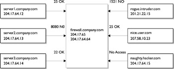
Figure 35-4: Basic firewall configuration blocking incoming and outgoing ports.
The Kernel Routing Table
The routing table maintains an index of routes to networks and routers that are available to the local host. Routes can be determined dynamically (by using RDISC, for example) or added manually by using the route or ifconfig command. These commands are normally used at boot time to initialize network services. There are three kinds of routes: host routes, which map a path from the local host to another host on the local network; network routes, which allow packets to be transferred from the local hosts to other hosts on the local network; and default routes, which pass the task of finding a route to a router. Both RIP and RDISC daemons can use default routes. Dynamic routing often causes changes in the routing table after booting, when a minimal routing table is configured by ifconfig while initializing each network interface, as the daemons manage changes in the network configuration and router availability.
EAN: 2147483647
Pages: 265