Doing More with Less (Bandwidth)
| Bandwidth on WAN links is regarded as a precious commodity because customers typically pay their service provider recurring monthly fees for that WAN bandwidth. Therefore, a VoIP design goal is to make the most efficient use of the WAN's scarce bandwidth. This section addresses QoS mechanisms that make your traffic better stewards of WAN bandwidth. Specifically, this section introduces you to compression technologies, which send fewer bits across the link, and link fragmentation and interleaving technologies, which fragment large payloads to reduce the serialization delay experienced by smaller payloads. First, let's discuss compression. The two broad categories of compression include
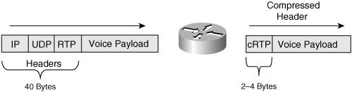
The goal of compression technologies is to increase the throughput over a WAN link, while reducing packet delay. However, particularly with payload compression approaches (that is, when the actual data, not just the header, is compressed), the time required by lower-end routers (for example, 2600 Series routers) to run the compression algorithm might actually increase the overall delay. Fortunately, these routers might support hardware acceleration modules, which you can add to dramatically improve the router's ability to perform compression in a timely manner. For example, a Compression Advanced Integration Module (CAIM) is available to offload compression tasks from 2600 Series routers. This chapter, however, focuses on header compression. With header compression, the header of a packet shrinks from approximately 40 bytes in size to approximately 3 to 5 bytes (for TCP header compression) or 2 to 4 bytes (for RTP header compression [cRTP]), as illustrated in Figure 6-25. Compressing 40 bytes down to as little as 2 bytes might seem nearly impossible. Back in the early 90s, hard drive compression swept the industry. I remember the thrill I felt after running compression software on my 80 MB hard drive, giving me approximately 160 MB of usable storage space! (Ah…how times have changed…) I was very satisfied to receive a 2:1 compression ratio. So, how do header compression technologies offer 20:1 compression ratios? Here's the secret. The routers are not technically doing compression. Figure 6-25. RTP Header Compression Header compression technology makes the observation that most information contained in a packet's header remains the same during the session (for example, during a phone call). Consider the source and destination IP addresses in the header. Those addresses don't change during a session. What about TCP or UDP port numbers? Usually, they don't change either. The payload type information contained in an RTP packet doesn't change. So, why send the same information in every single packet? Header compression technology saves a tremendous amount of bandwidth by not sending this repetitive information. A compressed voice header, for example, only carries such information as UDP checksums and a session context ID (CID), which identifies the flow that the packet is a part of. Another QoS mechanism useful for slower link speeds is Link Fragmentation and Interleaving (LFI). Consider a 1500-byte data frame being sent out of a 64-kbps serial interface. The interface, in this case, needs 187 ms just to place that data frame on the wire. If there is a smaller voice packet sitting behind that data frame, the voice frame experiences excessive delay before it is ever placed on the wire, resulting in jitter. LFI mechanisms fragment larger payloads to specified fragment sizes and then interleave the smaller payloads in among the fragments, greatly reducing the serialization delay experienced by the smaller payloads, as shown in Figure 6-26. Figure 6-26. Link Fragmentation and Interleaving As a metaphor, imagine you're driving your super-fast sports car, and you pull up behind one of those big triple tractor-trailers at a traffic light. These triple tractor-trailers connect three separate trailers to a single tractor (that is, a truck pulling three trailers). After the traffic light turns green, the massive tractor-trailer slowly enters the intersection. Meanwhile, you're being delayed and are possibly about to experience road rage. However, what if the trucking company had taken those three trailers and placed each one of them behind a separate tractor? If it had, there would be three separate tractor-trailer vehicles on the road. In your sports car, you might be able to pass one or two of those tractor-trailers and, as a result, get through the traffic light quicker. That's exactly what LFI mechanisms do. LFI mechanisms break up the big payload (the triple tractor-trailer in our metaphor) and interleave the relatively tiny voice packets in amongst those fragments (your sports car passing some of the individual tractor-trailers in our metaphor), resulting in decreased serialization delay and improved voice quality. The three primary LFI mechanisms supported by Cisco are
The serialization delay goal when configuring an LFI mechanism is delay in the range of 10 to 15 ms. To determine the serialization delay for a specific frame size on a specific link speed, use the formula:
The reason the frame size gets multiplied by eight is to convert bytes into bits. Consider a frame size of 512 bytes on a link speed of 128 kbps:
This calculation shows that 32 ms elapse while a 512-byte frame exits on a 128-kbps interface. |
EAN: 2147483647
Pages: 138