Signaling Systems
| Configuring Cisco Systems voice equipment to interface with other equipment requires an understanding of the signaling that conveys supervision between the systems. Proper troubleshooting also requires an understanding of these signaling systems. This section describes the various signaling systems used between telephony systems, such as common channel signaling and channel associated signaling. It also explores signaling between PBXs, signaling between PBXs and COs, and specialized signaling, such as ISDN. Channel Associated SignalingChannel associated signaling (CAS) is a signaling method commonly used between PBXs. Although this can manifest itself in many forms, some methods are more common than others. Signaling systems can also be implemented between a PBX and a Cisco voice device. T1 Channel Associated SignalingPBXs and Cisco devices use T1 and E1 interfaces to convey voice. Originally, this was the main purpose of T1, which carries signaling information using two methodologies: CAS and common channel signaling (CCS). Figure 2-31 illustrates the format of the T1 digital signal. Figure 2-31. T1 Digital Signal Format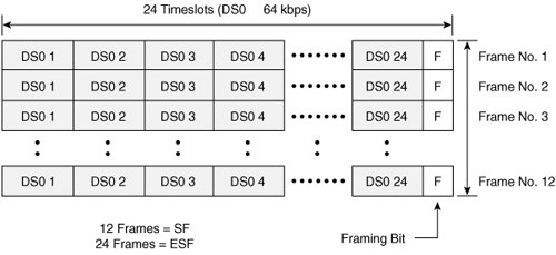 The characteristics of the T1 digital signal format are as follows:
Because each DS0 channel carries 64 kbps, and G.711 is 64 kbps, there is no room to carry signaling. Implemented for voice, the T1 uses every sixth frame to convey signaling information. In every sixth frame, the least significant bit (LSB) for each of the voice channels is used to convey the signaling, as shown in Figure 2-32. Although this implementation detracts from the overall voice quality (because only 7 bits represent a sample for that frame), the impact is not significant. This method is called robbed-bit signaling (RBS). When SF employs this method, the signaling bits are conveyed in both the 6th (called the "A" bit) and 12th (called the "B" bit) frames. For control signaling, A and B bits provide both near- and far-end off-hook indication. Figure 2-32. Robbed-Bit Signaling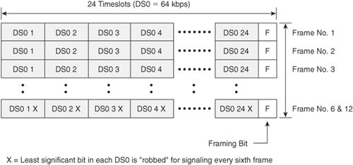 The A and B bits can represent different signaling states or control features (on hook or off hook, idle, busy, ringing, and addressing). The robbed bit is the least significant bit from an 8-bit word. ESF also uses RBS in frames 6, 12, 18, and 24 to yield four signaling bits, providing additional control and signaling information. These four bits are known as the A, B, C, and D bits. Because the signaling occurs within each DS0, it is referred to as in band. Also, because the use of these bits is exclusively reserved for signaling each respective voice channel, it is referred to as CAS. The robbed bits, depicted in Figure 2-33, are used to convey E&M status or FXS/FXO status and provide call supervision for both on hook and off hook. Figure 2-33. Channel Associated Signaling T1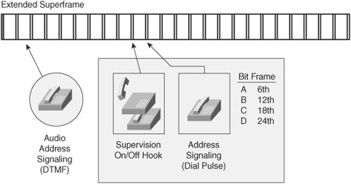 T1 CAS has the following characteristics:
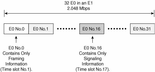
E1 Channel Associated SignalingIn E1 framing and signaling, 30 of the 32 available channels, or time slots, are used for voice and data. Framing information uses time slot 1, while time slot 17 (E0 16) is used for signaling by all the other time slots. This signaling format, illustrated in Figure 2-34, is also known as CAS because the use of the bits in the 17th time slot is exclusively reserved for the purpose of signaling each respective channel. However, this implementation of CAS is considered out of band, because the signaling bits are not carried within the context of each respective voice channel, as is the case with T1. E1 CAS is directly compatible with T1 CAS, because both methods use AB or ABCD bit signaling. Although the signaling for E1 CAS is carried in a single common time slot, it is still referred to as CAS because each individual signaling time slot represents a specific pair of voice channels. Figure 2-34. E1 Framing and Signaling In the E1 frame format, 32 time slots make up a frame. A multiframe consists of 16 E1 frames, as depicted in Figure 2-35. Figure 2-35. Channel Associated Signaling - E1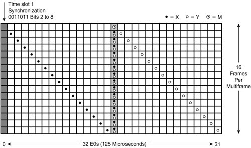 The time slots are numbered 1 though 32, although the channels are numbered 0 through 31, as shown in Figure 2-35. Multiframe time slots are configured as follows:
Common Channel Signaling SystemsCommon channel signaling (CCS) differs from CAS in that all channels use a common channel and protocol for call setup. Using E1 as an example, a signaling protocol, such as ISDN Q.931, would be deployed in time slot 17 to exchange call-setup messages with its attached telephony equipment, as seen in Figure 2-36. Figure 2-36. Common Channel Signaling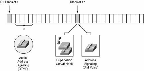 Examples of CCS signaling are as follows:
The following discussions elaborate on various CCS implementations. Note that proprietary implementations are not discussed because they vary widely among vendors. ISDNISDN (Integrated Services Digital Network) is an access specification to a network. You may have studied ISDN as an access method for dial-up data systems. Because it is a digital system, ISDN makes connections rapidly. ISDN can be implemented in two different ways: BRI (Basic Rate Interface) and PRI (Primary Rate Interface). BRI features two bearer (B) channels, while PRI supports 23 (for T1) or 30 (for E1) B channels. Each implementation also supports a data (D) channel, used to carry signaling information (CCS). The following are benefits of using ISDN to transmit voice:
Note ISDN BRI voice is commonly used in Europe, while ISDN PRI voice is used worldwide. Figure 2-37 shows the architecture of an ISDN network. The B channel carries information, such as voice, data, and video, at 64 kbps. The D channel carries call signaling between customer premises equipment (CPE) and the network, usually as the Q.931 protocol but sometimes as the QSIG protocol. Figure 2-37. ISDN Network Architecture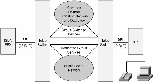 BRI operates using the average local copper pair. It uses two B channels and one signaling channel, which is written as 2 B + D. PRI implemented on T1 uses 23 B channels and one signaling channel, which is written as 23 B + D. PRI implemented on E1 uses 30 B channels and one signaling channel, which is represented as 30 B + D. ISDN's Q.931 protocol, which operates at Layer 3 of the OSI (Open System Interconnection) model, uses a standard set of messages to communicate, as illustrated in Figure 2-38. Figure 2-38. Layer 3 (Q.930/931) Messages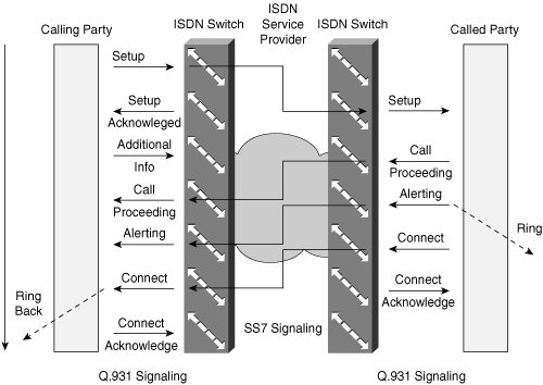 These standard messages cover the following areas:
Note ISDN Layer 3 messages, or Q.931, are carried within ISDN Layer 2 frames, called Q.921. Cisco ISDN equipment allows the administrator to monitor these messages as they occur using various debug commands. QSIGThe QSIG (Q Signaling) protocol is based on the ISDN Q.931 standard and provides signaling for private integrated services network exchange (PINX) devices. Figure 2-39 shows how different QSIG operations map to the OSI model. Figure 2-39. QSIG Protocol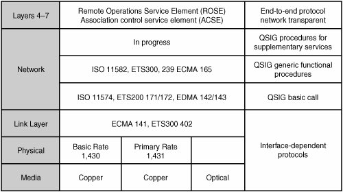 PINX includes everything from PBXs and multiplexers to Centrex. QSIG is implemented on PRI interfaces only. By using QSIG PRI signaling, a Cisco device can route incoming voice calls from a PINX across a WAN to a peer Cisco device, which can then transport the signaling and voice packets to a second PINX. ISDN PRI QSIG voice signaling provides the following benefits:
DPNSSBritish Telecom and selected PBX manufacturers originally developed the Digital Private Network Signaling System (DPNSS) in the early 1980s. It was developed and put into use before the ISDN standards were completed because customers wanted to make use of digital facilities as soon as possible. DPNSS operates over standard ISDN physical interfaces and is described in four documents:
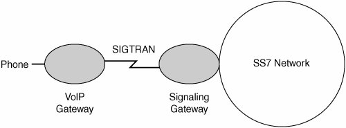
Note Cisco Systems supports DPNSS on various gateway platforms, such as the Cisco 2600, 3600, and 5300 series. DPNSS is not a common signaling system but is still in use in various parts of the world. SIGTRANSIGTRAN, as illustrated in Figure 2-40, is a signaling protocol defined in RFC 2719 and RFC 2960. It describes the way the IP protocol carries SS7 messages in a VoIP network. SIGTRAN relies on the Stream Control Transport Protocol at Layer 4 of the TCP/IP protocol stack. Figure 2-40. SIGTRAN Using SIGTRAN, a service provider may interconnect a private VoIP network to the public switched telephone network (PSTN) and ensure that SS7 signals are conveyed end to end. Note SIGTRAN is implemented on Cisco IP Transfer Point (ITP) equipment as well as the Cisco SC 2200 Signaling Controller. SS7The ITU-T (formerly the CCITT) developed SS7 in 1981. The primary functions and benefits of SS7 are as follows:
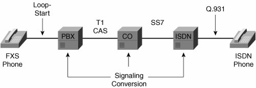
Figure 2-41 depicts an implementation of SS7. As a function of customer networks, SS7 can be implemented as CCS across a telephony network enterprise. Using Cisco equipment, service providers can implement SS7 on their networks. Cisco has developed several solutions that support off-loading IP traffic from public networks and that support the direct connection of network access servers to the PSTN using SS7 links. These solutions utilize the Cisco SC2200, BTS 10200, and AS5x00, giving service providers a proven and cost-efficient SS7 solution for connecting dial-access servers and voice gateways to the PSTN. Figure 2-41. SS7 Application Example The Cisco AS5x00 family provides carrier-class, high-density connectivity for VoIP and dial subscribers. The product set supports a wide range of IP services (including voice) and enables carriers and Internet service providers (ISPs) to cost-effectively support increased subscriber services and an increasing subscriber base. Signaling System InteroperabilityIn some implementations, it is necessary to convert from one signaling format to another. Conversion is necessary to allow different systems to signal each other. Figure 2-42 illustrates an example of signal conversion. Figure 2-42. Signal Conversion Example The FXS phone is using FXS loop-start signaling to connect to the PBX. The user dials 9 for an outside line, which carries the call on the T1 by using CAS. After the call reaches the CO, it travels via an SS7-signaled circuit to an ISDN switch. The call is then conveyed via Q.931 to the ISDN telephone at the called party location. Other conversion applications exist in voice telephony, and the telephony equipment must have the capability to perform these conversions transparently to the end users. |
EAN: 2147483647
Pages: 111