Analog-to-Digital and Digital-to-Analog Voice Encoding
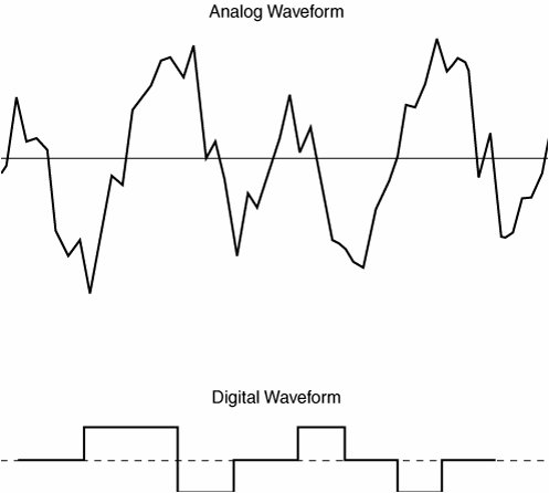
| This section covers the fundamentals of digitally encoding voice, specifically, the basics of voice digitization and the various compression schemes that are used to transport voice while using less bandwidth. Digitizing speech was a project first undertaken by the Bell System in the 1950s. The original purpose of digitizing speech was to deploy more voice circuits with a smaller number of wires. This evolved into the T1 and E1 transmission methods of today. Examples of analog and digital waveforms are presented in Figure 2-24. Figure 2-24. Analog and Digital Waveforms Table 2-3 details the steps to convert an analog signal to a digital signal.
The three mandatory components in the analog-to-digital conversion process are further described as follows:
This three-step process is repeated 8000 times per second for telephone voice-channel service. Use the fourth optional step, compression, to save bandwidth. This optional step allows a single channel to carry more voice calls. Note The most commonly used method of converting analog to digital is pulse code modulation (PCM), as described later in the "Voice Compression Standards" section of this chapter. After the receiving terminal at the far end receives the digital PCM signal, it must convert the PCM signal back into an analog signal. The process of converting digital signals back into analog signals includes the following two processes:
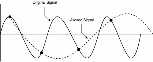
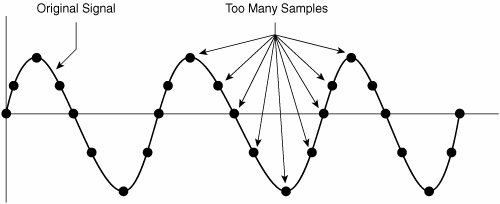
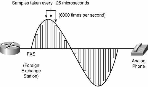
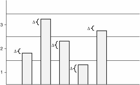
With this basic understanding of analog to digital conversion, this chapter considers the sampling, quantization, and encoding processes more thoroughly, beginning with sampling. Sampling and the Nyquist TheoremOne of the major issues with sampling is determining how often to take those samples (that is, "snapshots") of the analog wave. You do not want to take too few samples per second because when the equipment at the other end of the phone call attempts to reassemble and make sense of those samples, a different sound (that is, a lower frequency sound) signal might also match those samples, and the incorrect sound would be heard by the listener. This phenomenon is called aliasing, as shown in Figure 2-25. Figure 2-25. Aliasing With the obvious detrimental effect of undersampling, you might be tempted to take many more samples per second. While that approach, sometimes called oversampling, does indeed eliminate the issue of aliasing, it also suffers from a major drawback. If you take far more samples per second than actually needed to accurately recreate the original signal, you consume more bandwidth than is absolutely necessary. Because bandwidth is a scarce commodity (especially on a wide-area network), you do not want to perform the oversampling shown in Figure 2-26. Figure 2-26. Oversampling Digital signal technology is based on the premise stated in the Nyquist Theorem: When a signal is instantaneously sampled at the transmitter in regular intervals and has a rate of at least twice the highest channel frequency, then the samples will contain sufficient information to allow an accurate reconstruction of the signal at the receiver. Figure 2-27 illustrates sampling, as prescribed by the Nyquist Theorem. Figure 2-27. Nyquist Theorem While the human ear can sense sounds from 20 to 20,000 Hz, and speech encompasses sounds from about 200 to 9000 Hz, the telephone channel was designed to operate at about 300 to 3400 Hz. This economical range carries enough fidelity to allow callers to identify the party at the far end and sense their mood. Nyquist decided to extend the digitization to 4000 Hz, to capture higher-frequency sounds that the telephone channel may deliver. Therefore, the highest frequency for voice is 4000 Hz, or 8000 samples per second; that is, one sample every 125 microseconds. QuantizationQuantization involves dividing the range of amplitude values that are present in an analog signal sample into a set of discrete steps that are closest in value to the original analog signal, as illustrated in Figure 2-28. Each step is assigned a unique digital code word. Figure 2-28. Quantization In Figure 2-28, the x-axis is time and the y-axis is the voltage value (PAM). The voltage range is divided into 16 segments (0 to 7 positive, and 0 to 7 negative). Starting with segment 0, each segment has fewer steps than the previous segment, which reduces the signal-to-noise ratio (SNR) and makes the segment uniform. This segmentation also corresponds closely to the logarithmic behavior of the human ear. If there is an SNR problem, it is resolved by using a logarithmic scale to convert PAM to PCM. Linear sampling of analog signals causes small-amplitude signals to have a lower SNR, and therefore poorer quality, than larger amplitude signals. The Bell System developed the μ-law method of quantization, which is widely used in North America. The International Telecommunication Union (ITU) modified the original m-law method and created a-law, which is used in countries outside of North America. By allowing smaller step functions at lower amplitudes, rather than higher amplitudes, μ-law and a-law provide a method of reducing this problem. Both μ-law and a-law "compand" the signal; that is, they both compress the signal for transmission and then expand the signal back to its original form at the other end. To calculate the bit rate of digital voice, you can use the formula:
The result of using μ-law and a-law is a more accurate value for smaller amplitude and uniform signal-to-noise quantization ratio (SQR) across the input range. Note For communication between a μ-law country and an a-law country, the μ-law country must change its signaling to accommodate the a-law country. Both μ-law and a-law are linear approximations of a logarithmic input/output relationship. They both generate 64-kbps bit streams using 8-bit code words to segment and quantize levels within segments. The difference between the original analog signal and the quantization level assigned, as seen in Figure 2-29, is called quantization error, which is the source of distortion in digital transmission systems. Figure 2-29. Quantization Error Due to the quantization error, the recreated signal at the receiving end will experience quantization noise. The quantization noise is mostly insignificant since a single sample represents only 1/8000th of a second. However, frequent quantization errors will cause perceptible quantization noise. For this reason, the recreated signal at the receiving end is sent through a low-pass filter, which filters out the noise. Voice Compression StandardsTo conserve valuable WAN bandwidth, you can compress the quantized voice waveforms. Two categories of waveform encoding include:
Table 2-4 describes the CODECs and compression standards.
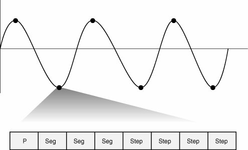
A common type of waveform encoding is pulse code modulation (PCM). Standard PCM is known as ITU standard G.711, which requires 64,000 bits per second of bandwidth to transport the voice payload (that is, not including any overhead), as shown in Figure 2-30. Figure 2-30. Pulse Code Modulation Figure 2-30 shows that PCM requires 1 polarity bit, 3 segment bits, and 4 step bits, which equals 8 bits per sample. The Nyquist Theorem requires 8000 samples per second; therefore, you can figure the required bandwidth as follows: 8 bits * 8000 samples per second = 64,000 bits per second Adaptive differential pulse code modulation (ADPCM) coders, like other waveform coders, encode analog voice signals into digital signals to adaptively predict future encodings by looking at the immediate past. The adaptive feature of ADPCM reduces the number of bits per second that the PCM method requires to encode voice signals. ADPCM does this by taking 8000 samples per second of the analog voice and turning them into linear PCM samples. ADPCM then calculates the predicted value of the next sample, based on the immediate past sample, and encodes the difference. The ADPCM process generates 4-bit words, thereby generating 16 specific bit patterns. The ADPCM algorithm from the Consultative Committee for International Telegraph and Telephone (CCITT) transmits all 16 possible bit patterns. The ADPCM algorithm from the American National Standards Institute (ANSI) uses 15 of the 16 possible bit patterns. The ANSI ADPCM algorithm does not generate a 0000 pattern. The ITU standards for compression are as follows:
Note CCITT is now called International Telecommunication Union Telecommunication Standardization Sector (ITU-T). Code excited linear prediction (CELP) compression transforms analog voice as follows:
Two forms of CELP include Low-Delay CELP (LDCELP) and Conjugate Structure Algebraic CELP (CS-ACELP). LDCELP is similar to CS-ACELP, except for the following:
Two of these subframes are combined into a 5-ms block for transmission. CS-ACELP is a variation of CELP that performs these functions:
Cisco VoIP environments typically leverage the benefits of G.729 when transmitting voice traffic over the IP WAN. These benefits include the ability to minimize bandwidth demands, while maintaining an acceptable level of voice quality. Several variants of G.729 exist. G.729 VariantsG.729, G.729 Annex A (G.729A), G.729 Annex B (G.729B), and G.729A Annex B (G.729AB) are variations of CS-ACELP. The G.729 Annex B (G.729B) variant adds voice activity detection (VAD) in strict compliance with G.729B standards. When this coder-decoder (CODEC) variant is used, VAD is not tunable for music threshold, meaning that a threshold volume level cannot be configured to pass voice while suppressing lower volume music on hold. However, when Cisco VAD is configured, music threshold is tunable. There is little difference between the ITU recommendations for G.729 and G.729A. All of the platforms that support G.729 also support G.729A. G.729 is the compression algorithm that Cisco uses for high-quality 8-kbps voice. When properly implemented, G.729 sounds as good as the 32-kbps ADPCM. G.729 is a high-complexity, processor-intensive compression algorithm that monopolizes processing resources. Although G.729A is also an 8-kbps compression, it is not as processor intensive as G.729. It is a medium-complexity variant of G.729 with slightly lower voice quality. G.729A is not as high quality as G.729 and is more susceptible to network irregularities, such as delay, variation, and tandeming. Tandeming causes distortion that occurs when speech is coded, decoded, and then coded and decoded again, much like the distortion that occurs when a videotape is repeatedly copied. CODEC ComplexityOn Cisco IOS gateways, you must use the variant (G.729 or G.729A) that is related to the CODEC complexity configuration on the voice card. This variant does not show up explicitly in the Cisco IOS command-line interface (CLI) CODEC choice. For example, the CLI does not display g729r8 (alpha code) as a CODEC option. However, if the voice card is defined as medium-complexity, then the g729r8 option is the G.729A CODEC. G.729B is a high-complexity algorithm, and G.729AB is a medium-complexity variant of G.729B with slightly lower voice quality. The difference between the G.729 and G.729B CODEC is that the G.729B CODEC provides built-in Internet Engineering Task Force (IETF) VAD and comfort noise generation (CNG). The following G.729 CODEC combinations interoperate:
|

EAN: 2147483647
Pages: 111