About Space Plans
|
Space plans can start out a lot like other floor plans and office layout diagrams. However, the Space Plan template is an application unto itself, and, frankly, this chapter only begins to describe its possibilities. The diagram you create might look like other Visio diagrams inasmuch as you can work with shapes. However, you’re probably better off thinking of space plans as a different entity altogether, because you’re not only creating a diagram, you’re building a model of a facility. Part of the model is visible in the shapes on the drawing page, but the heart of the model is behind the scenes in the associations you create between shapes, spaces, people, and assets.
In fact, you can take a regular floor plan or any Visio diagram and convert it to a space plan. The result is a visual database—a picture of your facility with an extra layer of tools underneath the diagram that let you track information about people, space, equipment, and assets, as Figure 26-1 shows. That information is probably something your organization already has in the form of an operations or human resources database. Visio can link your existing data source to shapes in a floor plan diagram. Shapes don’t have to be linked to an external data source; you can use Visio to enter information directly. In either case, with the facilities data, a floor plan becomes a model that can represent your office spaces, employees, network equipment, workstations, modular furniture, and more.
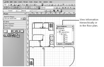
Figure 26-1: A Visio space plan looks like a floor plan but includes a built-in database of information about an organization.
Whenever you bring external data into the picture, you add power but also a layer of complexity to the diagramming task. Working with databases is a specialty, just as drafting or diagramming floor plans is a specialty. What Visio Professional provides is a way to tie the two specialties together. The Space Plan template is really designed for an applications developer or IT person in a facilities department, who can set up a model in Visio that represents his or her organization. Once a space plan is set up, it’s designed so that anyone can use it to locate people and assets. If you’re not a technician and you want to link your space plan to an existing database, you might require the services of your local database guru during the setup phase. On the other hand, Visio’s new Space Plan Startup Wizard, which we cover later in this chapter, simplifies the process, but it is not intended to be a solution to all your space plan needs.
In general, you set up a space plan as follows:
-
Open the Space Plan template in the Building Plan folder, and then create, import, or copy a floor plan into the diagram.
-
Define the spaces for which you want to track information. For example, each office in a floor plan can be a space. To designate an area as a space, you can use a space shape or import data.
-
Identify each space in your drawing with a unique identifier (the space ID) and a name. You can type these values in Visio or import the information.
-
Add the assets, equipment, and people you want to track in the plan. You can add shapes to do this and then enter the information manually using the Custom Properties window. You can also import existing information from a spreadsheet or database.
-
Associate the assets, equipment, people, and other resources with spaces. Visio can make these associations automatically if you import the information from a data source that includes location information, or you can indicate what goes where manually.
As you can see, a lot of flexibility is built into Visio’s space plans—you can use shapes, you can import data, or you can type information. More options usually means more complexity, and space plans aren’t exactly straightforward to set up. The five general steps just outlined translate into quite a few more specific steps, even if you opt for the more automated technique and import data. The sections that follow steer you through the winding paths you must take to get from a floor plan to a fully functioning, data-rich space plan. Then it does get easy: you relocate people and assets simply by dragging shapes in your plan. You can also create reports that show how assets are allocated or how different departments use space.
Using the Explorer Window
A space plan includes a unique Explorer window that displays all the information included in your facility model. In fact, the Explorer window can actually display more information than the facility drawing can. Everything you see in a floor plan—assets, people, equipment, and so on—is listed in the Explorer window, but the reverse is not necessarily true. You can store information about your facility in the Explorer window without using a shape to represent it on the drawing.
The Explorer window provides two views of your facility information, as Figure 26-2 shows:
-
The Categories tab This tab lists all the information in your space plan according to the following categories: Asset, Boundary, Computer, Equipment, Fixture, Furniture, Person, Printer, and Space.
-
The Spaces tab This tab lists all the physical spaces you’ve set up and the assets, people, and information associated with a particular space.
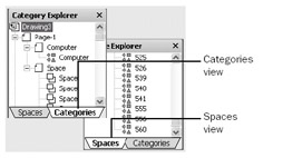
Figure 26-2: You can track resources in your floor plan by category or by space in the Explorer window. Click a tab to switch views.
You can use the Explorer window to show where people and things are located in a floor plan, as Figure 26-3 shows. Right-click an item on the Categories or Spaces tab, and then choose Show. Visio pans the floor plan and selects the shape associated with the space, asset, or person. In addition, you can use the Explorer window to rearrange furniture and equipment and even move a person from one office to another—the drawing automatically reflects the changes.
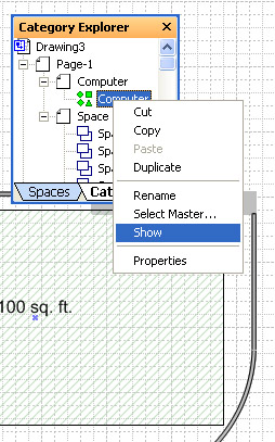
Figure 26-3: You can locate people, spaces, and assets listed in the Explorer window with the Show command on the shortcut menu.
Like other windows in Visio, you can dock the Explorer window against an edge of the drawing page, or you can move it into the stencil area or above or below the drawing window to give you more space to view the floor plan.
| Tip | Merge windows in space plans You might want to dock the Custom Properties window inside the Explorer window, because space plans can include facilities data in the form of custom properties. To do this, drag the Custom Properties window into the Explorer window. The Custom Props tab then appears with the Spaces and Categories tabs for easy access to all the information stored with a space plan. The easiest way to undock a window is to drag it by its tab to a new location. |
Understanding Shape Categories
When you drag shapes, such as furniture or computers, onto the drawing page, Visio automatically assigns them to one of the default categories. The exception is if you use a shape from a stencil not included with the Space Plan template; then you must assign it to the appropriate category with the Assign Category command. Unless shapes are assigned to categories, they don’t appear in the Explorer window and Visio doesn’t recognize them as resources in your facility.
| Cross-Reference | For details, see “Assigning a Category to a Shape,” page 788. |
| Note | Visio’s default categories aren’t flexible; you can’t rename them or define your own. Perhaps this will change in a future release, but for now Visio tracks everything by these category names. |
Understanding Unplaced Data
Resources in a space plan are placed when they appear on the floor plan drawing and are associated with a space or person. For example, you can drag a computer shape into the space that represents office 4N111 to place the computer and associate it with that office space, as Figure 26-4 shows. The Explorer window also includes a category named Unplaced Data. Sometimes when you import facilities or employee information from an external data source, the information is added to the underlying model as unplaced data but doesn’t appear on the floor plan drawing.
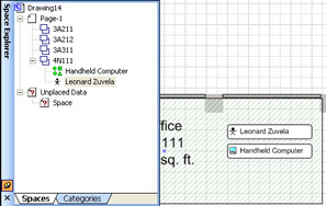
Figure 26-4: Placed resources—such as the handheld computer and the employee in this office—appear in the drawing. Because they’re associated with office 4N111, they are also listed under the appropriate space in the Explorer window.
Placing and associating resources are key concepts to working successfully with the model of your facility that the Visio drawing file represents. The Explorer window shows all the information in your space plan; the floor plan drawing might not. You can drag an item from the Unplaced Data list in the Explorer window onto the page to create a shape for it and “place” it. The Explorer window is then updated to show where you’ve placed it. If you move shapes around in the drawing, such as moving a person shape to a new office, the data in the Explorer window is also updated.
| Note | If you delete a shape in the drawing, it’s deleted from the Explorer window and doesn’t return to Unplaced Shapes. |
|
EAN: 2147483647
Pages: 209