ROUTING DOMAIN NUMBER DISCOVERY AND NETWORK MAPPING FOR IGPS
| | ||
| | ||
| | ||
While discovering the routing domain number for the internal gateway routing protocols, such as Open Shortest Path First (OSPF), would not provide you with a wealth of information supplied by investigating BGPv4 autonomous systems, in many cases it is nevertheless necessary. If you plan to send malicious updates to the running IGP to reroute traffic or cause a DoS, you must know the routing domain number. You can discover it both passively by sniffing the routing updates and actively by querying the routing protocols that are running. In the process of discovery, you will also detect IGP running routers on the network and the routes they advertise, which is the second aim of this section.
Do not expect both methods to be efficient against routers on the Internet. The IGP's routing updates are not likely to fly freely across the Internet and get forwarded to your box, and the same applies to the responses for your active queries. Thus, this enumeration method is mainly for internal penetration testing (and internal or wireless attackers ). Expect to be within one hop from the routers enumerated. A possible exemption is when multicast traffic is forwarded outside the enumerated network and an active querying method is employed, although we have never encountered such cases on the real-world Internet.
Mapping RIP, IGRP, and IRDP
| Attack |
|
You can map these routing protocols by sniffing the network for routing updates and analyzing the packets received. However, the best (and probably the only) tool available to perform this task in an efficient manner is the autonomous system scanner (ASS), available from Phenoelit's IRPAS suite. ASS is capable of both passive and active router and routing domain discovery. In fact, when ASS is run in the active mode, it switches to passive sniffing after a scan is done. ASS supports both versions of RIP, Cisco proprietary Interior Gateway Routing Protocol (IGRP) and Enhanced Interior Gateway Routing Protocol (EIGRP), and ICMP Router Discovery Protocol (IRDP), an easy target for traffic redirection and DoS attacks on LANs.
Let's do a general ASS sweep (no pun intended) on the small testing LAN configured to show some of the capabilities of ASS:
Passive mode: # ./ass -i eth0 ASS [Autonomous System Scanner] $Revision: 1.24 $ (c) 2k++ FX <fx@phenoelit.de> Phenoelit (http://www.phenoelit.de) IRPAS build XXXIX passive listen ... (hit Ctrl-C to finish) >>>Results>>> Router 192.168.66.101 (RIPv2) RIP2 [ n/a ] unknown auth RIP2 [ n/a ] 0.0.0.0/0.0.0.0, next: 192.168.66.100 (tag 0, mtr 1) RIP2 [ n/a ] 192.168.66.9/255.255.255.255, next: 192.168.66.100 (tag 0, mtr 1) RIP2 [ n/a ] 192.168.77.0/255.255.255.0, next: 0.0.0.0 (tag 0, mtr 1) Router 192.168.66.100 (RIPv2) RIP2 [ n/a ] unknown auth RIP2 [ n/a ] 0.0.0.0/0.0.0.0, next: 0.0.0.0 (tag 0, mtr 1) RIP2 [ n/a ] 192.168.0.1/255.255.255.255, next: 0.0.0.0 (tag 0, mtr 1) RIP2 [ n/a ] 192.168.66.9/255.255.255.255, next: 0.0.0.0 (tag 0, mtr 1) RIP2 [ n/a ] 192.168.66.105/255.255.255.255, next: 0.0.0.0 (tag 0, mtr 1) Active mode: # ./ass -i eth0 -A -v ASS [Autonomous System Scanner] $Revision: 1.24 $ (c) 2k++ FX <fx@phenoelit.de> Phenoelit (http://www.phenoelit.de) IRPAS build XXXIX Scanning + scanning IRDP ... + scanning RIv1 ... + scanning RIPv2 ... + scanning IGRP ... + waiting for EIGRP HELLOs (12s) ... Continuing capture ... (hit Ctrl-C to finish) >>>Results>>> Router 192.168.66.100 (RIPv1 RIPv2) RIP1 [ n/a ] 0.0.0.0 (metric 1) RIP1 [ n/a ] 192.168.0.1 (metric 1) RIP1 [ n/a ] 192.168.66.9 (metric 1) RIP1 [ n/a ] 192.168.66.105 (metric 1) RIP2 [ n/a ] unknown auth RIP2 [ n/a ] 0.0.0.0/0.0.0.0, next: 0.0.0.0 (tag 0, mtr 1) RIP2 [ n/a ] 192.168.0.1/255.255.255.255, next: 0.0.0.0 (tag 0, mtr 1) RIP2 [ n/a ] 192.168.66.9/255.255.255.255, next: 0.0.0.0 (tag 0, mtr 1) RIP2 [ n/a ] 192.168.66.105/255.255.255.255, next: 0.0.0.0 (tag 0, mtr 1) Router 192.168.66.101 (RIPv2) RIP2 [ n/a ] unknown auth RIP2 [ n/a ] 0.0.0.0/0.0.0.0, next: 192.168.66.100 (tag 0, mtr 1) RIP2 [ n/a ] 192.168.66.9/255.255.255.255, next: 192.168.66.100 (tag 0, mtr 1) RIP2 [ n/a ] 192.168.77.0/255.255.255.0, next: 0.0.0.0 (tag 0, mtr 1)
From this output, you can see that two routers are running Routing Information Protocol (RIP) on the network. Authenticated RIPv2 is used, even though the authentication method ( ip rip authentication mode md5 ) was not determined. If the authentication was plaintext (a security hole), the password would have been shown in the output. In active mode, router 192.168.66.100 does respond to RIPv1 requests telling about the hosts it knows , while router 192.168.66.101 ignores these requests. This shows the usefulness of the active mode, since in the passive mode ASS could not discover that router 192.168.66.100 supports RIPv1, which is a vulnerability. RIPv1 information is simple route and metric. To the contrary, RIPv2 also transmits the netmask , next hop, and tag. Since the routing domain number is not currently used with both RIP versions, [n/a] is shown instead of the domain number.
We can remove RIPv2 authentication with the following:
cisco-2611b(config)#int e0/0 cisco-2611b(config-if)#no ip rip authentication mode md5 cisco-2611b(config-if)#no ip rip authentication key-chain test_auth
The only change we see in active mode ASS output is the absence of the " unknown auth " line. Nevertheless, when we look at the packets' exchange using tcpdump and Ethereal, when the authentication is on, RIPv2 responses to ASS contain only authentication data trailer. When RIP authentication is turned off, we can see the actual routes sent back to the requesting host. But since we can see the very same routes via passive sniffing whether the RIP authentication is on or off, this does not bring significant difference to the scan output observed .
Let's have a look at what is going on when we scan with ASS from that router's side (authentication off):
cisco-2611b#terminal monitor cisco-2611b#debug ip rip events RIP event debugging is on Now the active mode scan is on: 000051: 2w2d: RIP: ignored v1 packet from 192.168.66.102 (illegal version) 000052: 2w2d: RIP: received v2 update from 192.168.66.100 on Ethernet0/0 000053: 2w2d: RIP: Update contains 4 routes 000054: 2w2d: RIP: ignored v1 packet from 192.168.66.102 (illegal version) 000055: 2w2d: RIP: received v2 request from 192.168.66.102 on Ethernet0/0 000056: 2w2d: RIP: sending update with long TTL 000057: 2w2d: RIP: sending v2 update to 192.168.66.102 via Ethernet0/0 (192.168.66.101) 000058: 2w2d: RIP: received v2 request from 192.168.66.102 on Ethernet0/0 000059: 2w2d: RIP: sending update with long TTL 000060: 2w2d: RIP: sending v2 update to 192.168.66.102 via Ethernet0/0 (192.168.66.101) 000061: 2w2d: RIP: sending v2 update to 224.0.0.9 via Ethernet0/0 (192.168.66.101)
This router does not support RIPv1; thus version 1 requests are treated as illegal and ignored. The update from 192.168.66.100 is legitimate . It does not trigger any response. The request from 192.168.66.102 is ASS, and it triggers a response with long Time to Live (TTL) value. This response is sent selectively to our ASS-ing host. It is followed by an update to the multicast address used by RIPv2.
How does ASS trigger RIP responses? It sends RIPv1 and RIPv2 request packets with the infinity metric 16, unspecified address, address family, route tag, netmask, and next hop (Figure 4-19).
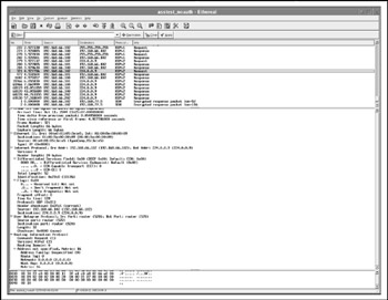
Figure 4-19: Querying RIP with ASS
In addition, ASS sends two ICMP type 10 (router solicitation) packets to 255.255.255.255 to discover whether IRDP is running on the network. It also tries to bruteforce the IGRP routing domain number by sending IGRP requests with routing domain numbers incrementing from 0 to 65535. Figure 4-20 shows the second IGRP request in a row, with routing domain number 1.
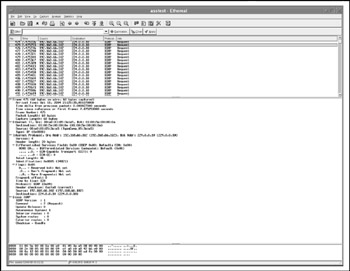
Figure 4-20: IGRP routing domain number bruteforcing
No EIGRP bruteforcing can be seen during the active mode ASS scan in our example. This is because, by default, ASS listens for EIGRP HELLO packets, and only after receiving them does it start scanning for the EIGRP routing domain directly against the router that advertised itself by sending EIGRP HELLO. Currently, no EIGRP is running on the testing network, thus no EIGRP bruteforcing takes place. If you want ASS to bruteforce EIGRP routing domain numbers independently of the presence of HELLO packets, use the -M option. Generally, ASS is options-rich:
# ./ass ./ass [-v[v[v]]] -i <interface> [-ApcMs] [-P IER12] [-a <autonomous system start> -b <autonomous system stop>] [-S <spoofed source IP>] [-D <destination ip>] [-T <packets per delay>] [-r <filename>]
You can increase the level of output verbosity by adding -v[v[v]] . Choose from which interface and IP the scan is going to run, select a specific supported protocol instead of scanning for all of them as per the preceding examples, choose a particular router to scan ( -D ), choose a range of routing domain numbers to bruteforce, and so on. The supported protocols are assigned as follows :
I = IGRP E = EIGRP R = IRDP 1 = RIPv1 2 = RIPv2
Don't forget to wait for a few minutes after going into "passive listen" or "Continuing capture" before aborting the tool to see the output. This will ensure that ASS has captured all the routing updates and query responses currently traversing the tested network. As to the verbosity level used when scanning in active mode, we suggest setting either -v or -vv . After all mapping is done, whether actively or by passive sniffing, get a piece of paper and draw the scheme of the network layout as you see it from the routing protocol. This is easy with RIP, which uses hops as a metric, and it's a bit more complicated with IGRP and EIGRP, which usually rely on the bandwidth and delay for route's cost estimation.
Enumerating OSPF
| Attack |
|
ASS does not enumerate OSPF. OSPF is a complex and interesting IGP that can provide a wealth of information about the networks it serves and become a target for efficient routing attacks. It is a hierarchical protocol with support of multiple areas of different types and significance. Investigating OSPF routing can tell us a lot about the network topology, links, bandwidth, second and even first network layers , routers with specific OSPF roles, and OSPF areas assignment. To enumerate OSPF, we can use the following methods:
-
Running OSPF- related show and debug commands on a router under your control
-
Querying involved routers via SNMP for OSPF-specific information
-
Passively sniffing the traffic (for example, with Ethereal)
-
Passively sniffing the traffic but using some tricks to trigger routing update floods
The first approach is easy, provided that you have managed to penetrate a router running OSPF. The commands you would like to check out include these:
show ip route show ip protocols show ip ospf show ip ospf database show ip ospf interface show ip ospf neighbor detail show ip ospf border-routers show ip ospf virtual-links
The second approach also requires a certain level of access to the routers on the enumerated network, at least knowing a valid read-only SNMP community (usually public) enabled on these routers. Everything you need to know about using SNMP to query and alter OSPF routing is described at the Cisco web site "OSPF Configuration Management with SNMP" at http://www.cisco.com/en/US/tech/tk869/tk769/technologies_white_paper09186a00801177ff.shtml . However, investigating OSPF routing peculiarities using the NET-SNMP snmpwalk tool manually is timeand effort-consuming. But there is a wonderful and easy-to-use SNMP-based OSPF enumeration tool, which is free, colorful , and runs in Windows. This tool is Polyphemus ( http://www.dia.uniroma3.it/~polyph/ ). Polyphemus allows you to look inside the OSPF routing domain and explore the areas, separating routers, and physical links between them. To install Polyphemus, you need a Windows 2000 machine (we ran it using vmware) and Java Software Development Kit (SDK) for Windows, which can be obtained from http://www.java.sun.com/j2se/ as well as other mirror sites.
After unpacking Polyphemus, copy the polifemo directory to C: and run the startServer.bat script. You should see a CLI interface; wait until it displays the "PolifemoServer bound in registry" message, indicating that the server is running. Then run the startClient.bat script and begin exploring by choosing Discovery OSPF and then Inter-Area or Intra-Area Connections, and following the instructions presented by an appropriate OSPF Discovery Wizard. An OSPF area number, as well as router IP or investigated network address range, can be given to the tool for investigation. We will not bombard you with a multitude of Polyphemus output screenshotsthe tool's web site presents a vast variety of those in the Snapshot Gallery section and even has a downloadable clip of Polyphemus in action.
But what if you don't have access to any of the routers on the network and failed to guess a valid SNMP community? Well, "if in doubt, sniff it out." (Note: Please do not apply this rule to unknown powdery substances.) Passive sniffing should suffice in the majority of cases. The OSPF HELLO packets and routing updates are sent to specific multicast addresses registered for use by this routing protocol and should be universally sniffable on a switched network, unless second layer control of multicast traffic propagation using Cisco Group Management Protocol (CGMP; see http://www.cisco.com/warp/public/473/22.html#cgmp ) is employed. The HELLO packets are sent every 10 or 30 seconds, depending on the network type (more on this will follow in the "Analyzing OSPF Enumeration Data" section), and you won't wait for long before seeing them flying by. To the contrary, OSPF routing updates are sent every 30 minutesif the routes do not change. If a route goes down or a new route appears, OSPF will propagate the information about the change across the network. Of course, when enumerating, you want to see the whole network topology table and not just the current change in the routing topology. Thus, you are limited to two options:
-
Waiting until the regular 30-minute update
-
Connecting a new OSPF router to the network (or emulating this event by sending forged OSPF packets)
Of course, if you are running an internal security audit, you can walk in with a preconfigured Cisco router in your hands and plug it in. How practical is this method to a hacker? Actually, this is not such an impossible task. If a hacker manages to break into a UNIX/UNIX-like machine on the same network, she or he can install routing software (for example, Quagga for Linux) and have a "black hat router" ready for action. (The installation and malicious use of open source routing suites is outlined in detail in the last chapter of this book.)
Alternatively, a hacker can be a malicious employee or use social engineering to obtain physical access to the network and plug in a pocket router built on a Linux PDA (Sharp Zaurus, iPAQ). Or, even better, he or she can plug in a rouge wireless device (USB dongle in ad hoc mode, mini-access point, Ethernet-to-wireless bridge) to connect the "malicious router" to the network while being outside the network's premises. Of course, one would not go that far just to enumerate OSPF routing, but doing this is one of the advantages of having a host under your control on the target network, whatever means were used to obtain such control. (By the way, we did encounter large, wide-open 802.11 networks running unauthenticated OSPF in the wild. It seems that some people never learn, no matter what.)
Apart from installing a routing suite on a hacked or rouge host, an attacker can emulate a new router joining the network by sending a sequence of packets typical for an OSPF handshake that takes place when a new router joins the network. Such a process can be emulated by using Nemesis, Spoof, or IPSorcerythe tools we are going to use a lot in the last chapter of this book. However, in our experience, this is more cumbersome than configuring Quagga, MRT, BIRD, or Gated.
Analyzing OSPF Enumeration Data
| Attack |
|
The first things you are going to see are OSPF HELLO packets. OSPF HELLO isn't a simple keepalive-type protocol and provides a wealth of information. The HELLO packets contain the following:
-
Router ID This is the IP of the router's loopback interface or the highest IP address on the router.
-
HELLO Interval This is the time between sending HELLO packets.
-
Router Dead Interval After this time passes , a neighbor router is considered to be unreachable.
-
Neighbor This is the IP address of the neighbor router.
-
Area ID This is the OSPF network area number, presented either as decimal or in an IP-like notation (1 and 0.0.0.1, 10 and 0.0.0.10 are the same).
-
Router Priority This is initially a Cisco proprietary value, now outlined in RFC 2328, that allows you to set a higher priority on a router without being dependent on the IP values.
-
Designated Router This is the IP address of the Designated Router (DR)the main router in the OSPF area.
-
Backup Designated Router This is the IP address of the Backup Designated Router (BDR), selected to take the DR function in case it goes down.
-
Authentication This field defines a type of authentication used by OSPF (none, plaintext password, or MD5 hash).
-
Stub Area Flag When this flag is set, the network area is a stuban OSPF cul-de-sac.
Every single parameter in this list is important for network enumeration.
The first thing you need to look at is whether authentication is used. If not, you can freely inject malicious routing updates into the network. Then, have a look at where DR and BDR are present, if they are present. A DR maintains all neighbor connections in the area to reduce the need for having the full mesh of connections. It is selected as a result of elections via the HELLO protocol and uses a specific multicast address 224.0.0.6, as well as "all OSPF routers" 224.0.0.5 address. This is the router a hacker who wants to reroute traffic would be after. If the network is correctly configured, this is the most powerful and resourceful router in the area. BDR should be the same in terms of its resources and configuration or come close to it. If the area ID is 0, you are on the OSPF backbone, where all network traffic is passing and can be attacked . If you are not in area 0, you want to get there. Have a look at various routing updates sniffed and see which ones have originated from area 0 and which IP range is the backbone.
Now let's determine the network topology and type. If the routing updates are sent to 224.0.0.5 / 224.0.0.6, both DR and BDR are present, HELLO interval is 10, and Dead Interval is 40 seconds, then it is a broadcast-supporting, multi-access, fully meshed network such as Ethernet or its emulations, such as LANE (Ethernet-over-ATM). If with the very same settings DR and BDR are absent (and so is the traffic to/from 224.0.0.6), it is a point-to-point link with broadcast support, likely a serial line. Point-to-multipoint broadcastsupporting star networks, for example serial lines with multiple subinterfaces, are similar to point-to-point links by their OSPF characteristics, but the HELLO interval and Dead interval are 30 and 120 seconds.
Point-to-point nonbroadcast networks (Frame Relay, X.25, ATM links) will also have these HELLO and Dead interval values; however, you won't see any broadcast or multicast traffic (surprise!) and all HELLO and routing update packets will be sent to the unicast addresses of participating routers. Multi-access nonbroadcast networks (such as fully-meshed Frame Relay, X.25, and ATM WAN clouds) have the same HELLO and Dead intervals with point-to-point nonbroadcast networks, but DR and BDR are there.
To reinforce your estimates about the physical layer of the enumerated network, calculate the bandwidth of its links from the OSPF cost parameter in the routing updates. The cost (also called metric ) of an interface in OSPF is inversely proportional to the bandwidth of that interface, and the formula used to calculate the cost is 100,000,000/bandwidth in bps. One hundred Mbps (Fast Ethernet) would have a cost of 1, a T1 line has a cost of 64, and a 56 Kbps dial-up link has a cost of 1785. Knowing the bandwidth is helpful in understanding what kind of network are you remotely sniffingfor example, frame relay, multiple subinterfaces, star topology, nonbroadcast media, multiple 128 Kbps circuits, or T1 pipe. Neat!
One thing that remains to be enumerated is the OSPF areas. You need to do this to know where you are and where you can get to on the network. You would also want to enumerate routers with special roles in multi-area OSPF routing (no, we do not refer to DR and BDR in this case).
To summarize, OSPF areas can be the following:
-
The backbone area ID 0; it connects all other areas together.
-
An ordinary area, connected to the backbone.
-
A stub area, mentioned earlier when we discussed HELLO packets. External networks redistributed from other routing protocols into OSPF are not allowed to be flooded into a stub area. Routing from the stub area to the outside world is based on a default route. Stub areas cannot carry through virtual links connecting distant areas to area 0.
-
A totally stubby area. This is a Cisco proprietary solution that extends the concept of stub area to further reduce the size of a routing table inside an area. No external and summary routes propagate into the totally stubby area, and the only way out of it is a default route. The presence of this area indicates that all deployed routers are of Cisco make and are likely to be positioned on a remote site/branch network with a single link to the central site.
-
A not so stubby area (NSSA). NSSA is a stub area that allows the injection of external routes in a limited fashion into the stub area. This could be a network branch that has its own Internet connection to use for itself without advertising it to the backbone. There is a good chance that egress filtering at such connection would be less restricted than at the main site Internet link, and such a connection could be used for a backdoor/backchannel link to the corporate network.
In accordance to their position in the OSPF network hierarchy, routers also have specific roles. Area Border Routers (ABRs) connect two or more OSPF areas together and hold a full topological database for every area they connect. Autonomous System Boundary Routers (ASBRs) connect the OSPF domain to the outside world. ASBR is the only router that can redistribute OSPF routes into other routing protocols. It must reside in the area 0. In general, all routers positioned on area 0 are called backbone routers. All routers in other areas with all interfaces within one area are called internal routers. An internal router maintains a database of all subnets within the area and does not send routing updates outside of it. From the attackers' viewpoint, ABRs and ASBRs are the most interesting targets.
To determine the router's role and the area at which it is positioned, analyze linkstate advertisement (LSA) routing updates. Propagation of each of the seven LSA types is area-specific. By looking at which LSA types are present within an area and from which router they originate, you can determine the area type and router role:
-
Type 1 LSA is called router link . It propagates routing data to all other routers within a single area.
-
Type 2 LSA is the network link . It is also flooded within a given area but is sent only by the designated router to all routers with which this router has a neighbor relationship.
-
Type 3 LSA is the network summary link . These LSAs are sent by ABR routers between the areas and summarize IP ranges from one area to another.
-
Type 4 LSA is an external ASBR summary link . The ABR sends this LSA type to ASBR, and its purpose is to advertise the metric (cost) between these two routers.
-
Type 5 LSA is an external link LSA generated by the ASBR to advertise routes to other OSPF domains, whether OSPF or static.
-
Type 6 LSA is a group membership link entry generated by multicast OSPF routers.
-
Type 7 LSA ( NSSA external LSA ) is sent by ASBR in the NSSA. It is very much like the type 5 LSA but is not propagated outside the not so stubby area. Seeing Type 7 LSAs is a telltale sign that you are sniffing within one.
To identify other areas, take the following into account:
-
Stub area routers set a stub flag in HELLO packets. There are no LSA types 4 and 5 within a stub area.
-
Totally stubby areas block LSA types 3, 4, and 5.
-
Not so stubby areas block LSA types 4 and 5 and propagate LSA type 7.
Hopefully, by now you can make sense out of those tcpdump (or Kismet) dumps with OSPF packets in them and understand your position on the network and its topology, identify interesting routers for further exploitation, and determine whether OSPF itself is vulnerable to attacks. As with other IGPs, it pays to draw the network diagram as OSPF sees it and label OSPF areas, router roles, and bandwidth for each advertised interface. An automatic tool to do such packet capturebased mapping for various IGPs in detail awaits its developers. We wish we had more free time.
Countermeasures for IGP Enumeration
| Countermeasure | As in the BGPv4 case, you can't do much about some of these attacks. However, one obvious thing to do is to restrict the spread of routing updates on the need-to-receive basis. By no means should the routing updates cross the boundaries of your network and be sniffable outside. To prevent that, use route distribution lists and passive interfaces, as we describe in the last chapter of the book. Another thing covered there is enabling proper routing updates authentication. While authenticating updates will not stop attackers from sniffing them and mapping the network, some active query methods can be thwarted if packets from unknown routers are dropped. |
In terms of development, it makes perfect sense to add the signatures of active routing enumeration to a variety of IDS tools such as Snort. A description of packets sent by ASS, as outlined in this chapter, should be helpful to anyone embarking on such a project. In general, a database should exist containing all legitimate router addresses on the network, and any routing update not coming from an address in the database should trigger an IDS response.
A lot of data discussed in this chapter is related to sniffing the network and analyzing the bypassing routing traffic to map the network and identify its weak points. A logical step to prevent this is to detect and eliminate sniffers on your network. Many tools can be used to accomplish that. One such program is ARP Promiscuous Node Detection (APD):
# ./apd -s 192.168.77.5 -e 192.168.77.6 -d eth0 APD v1.1b : ARP Promiscuous Node Detection. Written by: Dr.Tek of Malloc() Security -----[ APD starting ]----- ==> Probing host: 192.168.77.5 ==> 192.168.77.5 is not in promiscuous mode. ==> Probing host: 192.168.77.6 ==> 192.168.77.6 is in promiscuous mode. -----[ APD ending ] -----
In addition to the ARP response text, more complex programs can be used to detect promiscuous interfaces on LANs that use methods. Using such methods together allows system administrators to be more confident when searching for remote sniffers. Two open source tools we commonly use when looking for sniffers are sniffdet and sentinel . These tools offer two additional ICMP (ping response and ping latency) and a DNS (fake TCP connections) tests. (Since this goes outside the scope of this book, you can check these tools' documentation to understand how the listed tests work.) We have found the DNS and latency tests to be the most unreliable:
# sentinel -t 192.168.77.6 -f 1.1.1.1 -d [ The Sentinel Project: Remote promiscuous detection ] [ Subterrain Security Group (c) 2000 ] Device: eth0 Source IP Address: 192.168.77.5 Source Hardware Address: 0:4:75:e7:26:51 Target: 192.168.77.6 Fake Host: 1.1.1.1 Performing DNS Resolve test. Creating 10 fake TCP connections.......... Results: 192.168.77.6 tested negative to dns test. # sniffdet -t latency -v 192.168.77.6 ------------------------------------------------------------ Sniffdet Report Generated on: Fri Oct 15 18:05:36 2004 ------------------------------------------------------------ Tests Results for target 192.168.77.6 ------------------------------------------------------------ Test: Latency test Ping response with custom packet flood Validation: OK Started on: Fri Oct 15 18:05:23 2004 Finished on: Fri Oct 15 18:05:36 2004 Bytes Sent: 31747767 Bytes Received: 0 Packets Sent: 1274943 Packets Received: 105 RESULT: Normal time: 0.1 Flood round-trip min/avg/max: 0.2/2.2/2.8 ms Number of valid tests: #1 Number of tests with positive result: #0 But # sentinel -t 192.168.77.6 -f 1.1.1.1 -e [ The Sentinel Project: Remote promiscuous detection ] [ Subterrain Security Group (c) 2000 ] Device: eth0 Source IP Address: 192.168.77.5 Source Hardware Address: 0:4:75:e7:26:51 Target: 192.168.77.6 Performing ICMP etherping test Sending out 10 bogus ICMP ECHO packets.. Results: 192.168.77.6 tested positive to etherping test.
The results of an ARP test were also positive, and that host is, indeed, in promiscuous mode.
| Note | The mechanism of getting debug information on a Cisco router does not involve setting an interface into a promiscuous mode, and a taken-over router used to sniff the network via a debug ip packet or other debug command would not be detected by the tools we have outlined. |
| | ||
| | ||
| | ||
EAN: 2147483647
Pages: 117