CISCO NETWORK DESIGN MODELS: A SECURITY PERSPECTIVE
| | ||
| | ||
| | ||
Depending on the network size and purpose, Cisco recommends several practical design models. Every model has its security pros and cons and would greatly differ from other layouts when it comes to the safeguard availability, configuration, and maintenance somewhat similar to the order, positioning, and tactics used by an army that depend on the terrain on which the battle will be fought.
The Flat Earth Model
The flat earth model is a basic Layer 2based network design. In the past, it involved hubs, repeaters, and bridges. Nowadays, it is mainly a switch-based design, with a significant and ever-growing contribution from the wireless world represented by various 802.11 LANs and even 802.15 (such as Bluetooth) user access devices. Ideally, the flat earth design model should apply to limited- sized small office/home office (SOHO) LANs only, and CCDP guides recommend that this model not be used for networks with more than 50 nodes deployed. In practice, it is common to have several dozen users per broadcast domain, and the spread of wireless makes things even worse , since a modest 12-port switch may have a few access points plugged in, with 30 to 40 users per access point. Besides, many Cisco Catalyst switches are stackable and have high port density by themselves . If TCP/IP permits up to 500 users per LAN without a significant network performance degradation by the broadcast traffic, there would be network installers deploying such LANs without any consideration for management and security issues. For them, such an adventure is simply "using the full capacity of the Catalyst switches" and "getting the full value for money spent."
The flat earth model is considered to be highly insecure with a limited amount of measures that can be taken to protect it against an attacker armed with Ettercap, Hunt, Taranis, and similar tools. The traditional flat earth model safeguards include Media Access Control (MAC) address filtering and network segmentation with virtual LANs (VLANs). MAC address-based device authentication is elementary to bypass. However, assigning a predefined amount of MAC addresses to a switch port and manually assigning all of the allowed MACs is a useful, if laborious, task that stops dead the switch CAM table flooding attacks. Both IOS-style and Set/Clear Command Line Interface (CLI) Catalyst switches support MAC address filtering with extensive optionsuse it! Managing large MAC address filter tables is not that cumbersome if done in an intelligent way. You can extract and save the switch configuration file (or just the CAM table) and edit it on your workstation (perhaps using a small Perl script) to produce a new configuration file for upload on a switch. You don't even have to log in; ports and MAC addresses information from Catalyst switches is easily obtainable via Simple Network Management Protocol (SNMP), as explained at http://www.cisco.com/warp/public/477/SNMP/cam_snmp.shtml .
The benefits of VLAN segmentation are obvious; in the Cisco world, they are additionally reinforced by private VLANs (PVLANs) and VLAN access lists (VACLs). Private VLANs are supported on Catalyst 6000 switches running CatOS 5.4 or later as well as Catalyst 4000, 2980G, 2980G-A, 2948G, and 4912G models running CatOS 6.2 or later. VACLs are supported by Catalyst 6000 switches with CatOS 5.3 or later and can be implemented on a Catalyst 6500 at Layer 2 without the need for a router if a Policy Feature Card (PFC) is installed. Since the lookup and enforcement of VACL entries are performed in hardware, there is no performance penalty and the forwarding rate remains the same. A detailed discussion of PVLANs, VACLs, and Cisco countermeasures against various VLAN jumping attacks are included in Chapter 12, while their role in Catalyst 6500-based intrusion detection is outlined in Chapter 2. For now, keep in mind that PVLANs and VACLs can be a useful addition to your network security design plans; choose your Catalyst switches and software wisely to avoid necessary upgrades in the future.
A significant change to the approach to the flat earth network model security came about on June 14, 2001, when the Institute of Electrical and Electronics Engineers (IEEE) Standards Board approved 802.1x, a Layer 2 port-based network access control standard. 802.1x provides an authentication and authorization mechanism for devices connecting to switches, routers, or wireless access points. The actual authentication and authorization is done by a Remote Authentication Dial-In User Service (RADIUS) or Terminal Access Controller Access Control System (TACACS) server on behalf of the authenticator device (switch, router, or access point) and on the basis of credentials provided by a supplicant (the authenticating host). Figure 1-1 depicts a flat earth network model protected by 802.1x.
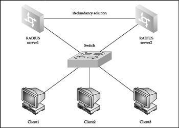
Figure 1-1: The flat earth design model
Two RADIUS servers provide authentication and authorization for end-user machines, and a switch serves as an authentication device. An additional link between the RADIUS servers provides resilience, and a failover protocol such as Cisco Hot Standby Router Protocol (HSRP) or Internet Engineering Task Force (IETF) Virtual Router Resilience Protocol (VRRP) must be used so that the network is operational if one of the authentication servers goes down. Keep in mind that HSRP and, to a lesser extent, VRRP have known security issues (see Chapter 13) that must be considered when deploying these protocols.
The switch on the diagram in Figure 1-1 can be any Catalyst switch that supports the 802.1x-based Cisco Identity-Based Networking Services (IBNS) technologyfor example, Cisco Catalyst 4000, 4500, or 6500 series. Alternatively, you can replace it by a Cisco Aironet wireless access point with a firmware supporting Wireless Protected Access (WPA) industry certification requirements. At the moment of writing, only WPA version 1 is available, but the 802.11i wireless security standard (on which the WPA is based) has been finally ratified and WPA version 2 development is in process. It doesn't matter which WPA version your access point is using, as 802.1x is employed to distribute and manage per-device or per-session secure keys as well as to authenticate wireless users. Thus, a secure or, in some cases, not-so-secure (see our book Wi-Foo: The Secrets of Wireless Hacking ) separation of devices on flat earth wireless LANs is achieved.
As you can see, there is far more to the "simple" flat earth network model security than usually meets the eye. Stay patient, and Part III of this book will uncover many Layer 2 hacks and counter-hacks applicable to the "plain" Cisco-based LANs.
The Star Model
The star model is a cost-effective network design with a single router acting as a focus point, providing connectivity for the whole network. Figure 1-2 shows a VPN concentrator instead of a casual router.
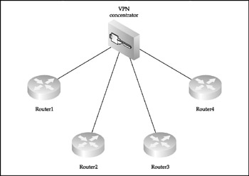
Figure 1-2: The star design model showing a VPN concentrator
The star model network design is very common for real-world VPN deployment when a concentrator in the central office provides secure links to the remote branch offices or telecommuters. Apart from being a VPN concentrator, the star core router is perfectly positioned for intrusion detection, traffic filtering, quality of service (QoS), and policy routing. Select this router and its operating system version and capabilities very carefully , since this is the heart of your network, its main bastion , and a single point of failure. Even from the most minimalist point of view, the router should be modular; should possess sufficient amount of memory and CPU horsepower to handle all traffic on your network, including its security processing (filtering, encryption, IDS analysis); should have dual redundant power supplies ; and should support Context Based Access Control (CBAC).
Cisco 7000 and higher series routers as well as Catalyst 5000 and above switches with routing switch modules (RSMs) installed are suitable for such a task. We strongly recommend that you deploy a pair of identical routers or switches running Cisco HSRP or VRRPsupported since the IOS version 12.0(18) STand supplied by power from two entirely different power sources for failover. Of course, all router/switch attack countermeasures discussed later in this book should be applied to protect the precious star core router, including physical access and social engineering safeguards. If you are really security conscious, a great (and expensive) option to consider is deploying a pair of highend PIX firewalls, such as PIX 535, as your star network core, where applicable.
The next thing you will need to do is ensure the presence of reliable out-of- band connections to the branch routers from the central site in case the main lines fail or fall victim to denial-of-service/distributed denial-of-service (DoS/DDoS) attacks. The cheapest solution would be a POTS (Plain Old Telephone Service) dial-in to the branch routers' AUX ports, but we recommend dial-on-demand Integrated Services Digital Network (ISDN) with snapshot routing preconfigured.
The Two- Tier Model
This network design model is essentially two star networks connected together, as shown in Figure 1-3.
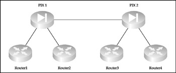
Figure 1-3: The two-tier design model
This model splits the control over the whole network between two sites. Thus, whoever controls the link between these sites controls the organization's IT infrastructure. Ensure that this link is protected with IPSecEncapsulating Security Payload (ESP) plus Authentication Header (AH)and is physically secure, if possible. Then deploy a failover out-of-band link between the tiers, such as the dial-on-demand ISDN backup link suggested in the star model section. (Of course, everything discussed in that section considering the security and general characteristics of the star core routers applies to the pair of devices on both sides of the tier-to-tier link.)
The Ring Model
This network design model, shown in Figure 1-4, ensures that every router has a single alternative link to the rest of the network.
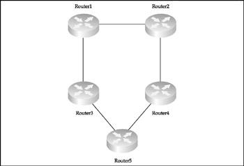
Figure 1-4: The ring design model
To utilize the ring structure efficiently , dynamic routing is required. In a purely Cisco environment, we recommend using Enhanced Interior Gateway Routing Protocol (EIGRP) for two reasons: this protocol can utilize five parameters to determine the route metric (flexibility) and supports unequal cost path load balancing (variance) and traffic sharing. It is also very fast when it comes to the route convergence due to the way the DUAL, an algorithm on which EIGRP is based, operates. When a valid route is removed, there is usually a feasible successor to replace it.
| Caution | Make sure that your routing protocol is secured against fake or malicious route update flood attacks, as described in Chapter 14; otherwise , your ring may fall apart like a house of cards. |
Use the ring routers as a distributed intrusion detection system (IDS), with more than one IDS management and centralized logging center symmetrically positioned along the ring. If you have spare cash, you can deploy Cisco IDS 4200 series sensors in between the ring routers, but in the majority of cases the IDS capabilities of Cisco IOS versions with Firewall Phase II support (the o3 identifier in the IOS name ) should suffice.
The Mesh and Partial Mesh Model
A full mesh network (Figure 1-5) is a packet kiddie 's nightmare and a Black Hat's dream.
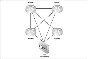
Figure 1-5: The full mesh design model
On the one hand, the large number of connections ( N = [ n ( n 1) 2], where n is a number of routers deployed) ensures the highest DoS/DDoS resilience as compared to other network design models. On the other hand, an attacker who manages to penetrate one of the full mesh network routers can easily sniff out the whole network and has multiple attack avenues to explore. Thus, every single router in a full mesh network is a major point of failure from the security perspective and should be protected just as well as the concentrator router on a star network. This creates high demands for both full mesh network security management procedures and security/general capabilities of the routers used. In addition, routing on large full mesh networks must be dynamic and can get very complex; the same applies to the defense against various routing protocols attacks. The partial mesh networks (Figure 1-6) are custom-designed solutions that compromise between full mesh pros (redundancy, scalability, and availability) and cons (cost of links and routers, and the complexity of general and security configuration, management, and maintenance).
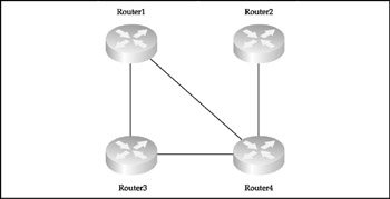
Figure 1-6: The partial mesh design model
The universal rule of a router with the most links demanding the highest level of protection and security maintenance applies to the partial mesh networks as well as to any other network design topology. Since partial mesh networks follow custom designs to satisfy specific corporate or organizational requirements, use your knowledge of networking and your common sense to determine where to apply or place access control devices and IDS sensors.
As to the dynamic routing on large partial mesh networks, it makes sense to employ a robust routing protocol that supports the separation of the network into areas of different topology, significance, and role. Undoubtedly, Open Shortest Path First (OSPF) is the best candidate for such a role, unless we are talking about very large multihomed networks with high policy routing requirements, which are typical Border Gateway Protocol (BGP) playgrounds.
| Note | The attacks against OSPF and BGP protocols and their Cisco implementations , together with the appropriate countermeasures, are complex topics covered in the final chapter of this book. |
Network Security Zones
Whatever your network topology model, to provide proper security you need to split the network into zones with different security significance. Most commonly, the network is divided into three security zones.
Most-Secure Zone
This part of the network stores the most sensitive information, such as Pretty Good Privacy (PGP) private keys. The access to this zone is restricted and tightly controlled. Apart from using a specialized firewall such as Cisco PIX to split this zone from the rest of network, we recommend that you encrypt all traffic belonging to the most-secure zone using IPSec with strong ciphers (such as 256-bit Advanced Encryption Standard [AES], or 128-bit Keyed-Hash Message Authentication Code [HMAC] SHA-1 or higher) selected. Dynamic and time-based router access lists can be used to restrict outside access to the zone on a user basis at defined time periods.
Secure Zone
This zone is where internal servers and workstations are positioned. A firewall should split this zone from the others. Such splitting should be done properly, including blocking of routing protocols packet propagation (passive interfaces and distribution lists on Cisco routers). Also, the firewall should have proxy Address Resolution Protocol (ARP) disabled and should not propagate Layer 2 information (such as Cisco Discovery Protocol [CDP] and Spanning Tree Protocol [STP] frames ) from the secure zone.
Demilitarized Zone (DMZ)
Public access servers are positioned at the DMZ. Access to the secure zone is accomplished via a firewall and is monitored for attacks. No access to the most-secure zone is allowed from the DMZ.
DMZ is likely to be the most important term used in network security architecture. It is usually a subnet positioned between public (the Internet) and private networks. DMZs are created in four common ways:
Three-Legged Firewall A three-legged firewall has at least three separate interfaces, such as PIX 515 and higher. Shown in Figure 1-7, it is probably the most common DMZ and offers a decent level of bypassing traffic control.
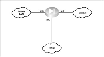
Figure 1-7: A DMZ based on a three-legged firewall
Outside Corporate Firewall A DMZ can also be placed outside the corporate firewall and connected directly to the public network, as shown in Figure 1-8. Such a setup depends entirely on the security of the servers deployed in the DMZ and is not recommended.
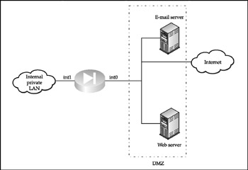
Figure 1-8: An outside DMZ
Dirty DMZ The so-called dirty DMZ, in which the public access servers (also called bastion hosts ) are connected to one of the interfaces of an enterprise edge router, is positioned outside the corporate firewall (Figure 1-9).
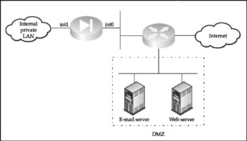
Figure 1-9: A dirty DMZ
A dirty DMZ is often set up when the firewall lacks a third interface or does not possess the ability to process the traffic load between the DMZ and the public network. It is considered to be a solution slightly more secure than an outside DMZ; however, in reality, a lot depends on the selection of an edge router from which the DMZ spans . You can make dirty DMZ reasonably secure, if the edge router
-
Has enough RAM and CPU power to do software-based traffic security processing
-
Has an IOS with extended security features, such as the o3 identifier
-
Is modular and security- related (such as firewalling or IDS) modules (or blades in "Ciscospeak") are installed and properly configured to do hardware-based, wire-speed traffic filtering or analysis
DMZ Between Stacked Firewalls Finally, a DMZ can be positioned between two stacked firewalls, as shown in Figure 1-10. This setup is sufficiently secure but can be expensive. To mitigate the expenses, a router with extended security capabilities, as described in the dirty DMZ section, can be deployed.
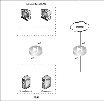
Figure 1-10: A two-firewall DMZ
The main problem with the two-firewall DMZ architecture is that the traffic from a secure private network has to traverse the less secure DMZ to reach outside space. A compromised bastion host provides attackers an opportunity to hijack and modify the sessions passing through DMZ. To mitigate such threats, private VLANs or even VPNs can be used.
IDS Sensor Deployment Guidelines
Another important part of network security architecture is correct deployment of intrusion detection sensors and management consoles. Chapter 2 outlines Cisco Secure IDS solution elements in some detail. Here we provide general guidelines on IDS components placement on a protected network:
-
The sensors should be distributed through all network layers to provide complete coverage of the whole IT infrastructure.
-
The sensors' bandwidth ability should never become exceeded and scalability issues must be taken into account. Multiple sensors can be stacked to meet growing bandwidth requirements.
-
The management console should be installed on a secured platform and placed in the most secure zone.
-
All traffic between sensors and management consoles must be both encrypted and authenticated. This includes both event alarms and sensor management traffic.
-
Deploying one sensor per VLAN is a good idea.
-
More than one management console should be deployed for redundancy and fallback reasons. A single sensor can send alarm messages to more than one console.
-
Cisco Secure IDS sensors can be configured to manage traffic-blocking functions on PIX firewalls. If that is the case, a sensor must be positioned close to the PIX firewall with which it communicates.
| Tip | Keep in mind that routers with extended security features on the IOS, routers and switches with IDS modules installed, and PIX firewalls can also serve as IDS sensors when needed. |
| | ||
| | ||
| | ||
EAN: 2147483647
Pages: 117