Planning How to Build
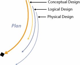
| Planning how to build a solution involves two work streams that build off a solution description contained in the functional specification. One work stream focuses on evolving a solution design from the conceptual solution defined during an Envision Track to detailed designs to enable implementation during a Build Track. The other work stream focuses on assembling various plans that collectively make up the master project plan. These two work streams are discussed next. Evolving a Solution DesignLead Advocacy Group: Architecture As detailed solution requirements are approved, a team starts to incrementally and systematically design a solution and what is needed to support delivery of a solution (e.g., test harnesses). Starting with the conceptual solution defined during envisioning and with requirements and design goals outlined in the functional specification, MSF proposes proceeding with a three-tiered design process: conceptual design, logical design, and physical design; each is discussed in the next few sections and is depicted in Figure 8-4. Each of these designing steps incrementally adds more clarity and design details to the overall solution design and the supporting collateral. This design process is not intended to be used serially where all of conceptual designing needs to be completed before moving on to logical designing and subsequently to physical designing of a solution. Conversely, as soon as a design step for an aspect of a solution is completed, designers proceed to another aspect or take the one they are working with to the next level of detail. The results of a design process are used to update a functional specification and possibly requirements. Figure 8-4. Evolving a solution design A design process is structured so that each design step validates the prior step and sets a foundation for the next step. It is expected that as a team advances through a design process, they might need to revisit prior design steps as errors, inconsistencies, and gaps are uncovered. Revisiting prior steps is not a sign of inadequate designing because usually a team is quickly trying to advance through a design process, and to finish a step to eliminate revisiting is often too costly. In fact, it is the heart of an iterative design process, and therefore revisiting should be encouraged. Conceptual DesignA conceptual design starts to bring clarity and adds a layer or two of detail to what was described during envisioning. Although the team still works at a conceptual level, a conceptual design incorporates the various aspects of what was covered in the functional specification (e.g., detailed description of a solution, detailed usage scenarios, QoS, test goals, design goals, and detailed requirements). A conceptual design introduces other aspects of designing, including high-level usability analysis, conceptual data modeling, process flows, context models, and initial technology implementation options. Table 8-6 provides an example of a typical use case. Table 8-7 provides an example of a supporting context model. Figure 8-5 provides an example of a matching process flow. Because there are many great books explaining these topics in detail, these examples are provided just for context.
Figure 8-5. Example of a process flow diagram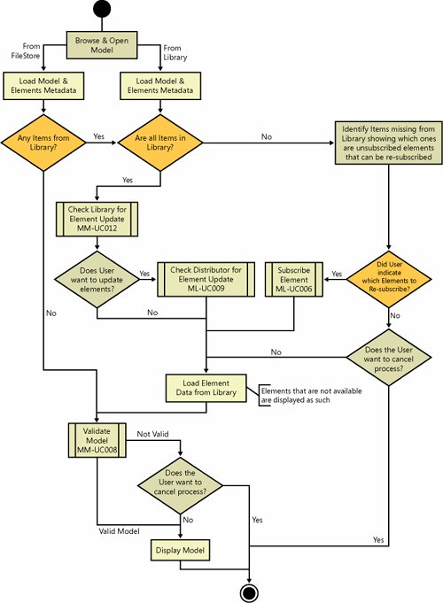 A conceptual design also maps out other aspects of a solution (e.g., usability evaluations). Each role contributes to the overall solution delivery effort and designs their deliverables (e.g., deployment strategies). For instance, a test group uses a functional specification and Envision Track outputs to form test strategies. Proceeding through a design process, a test team designs test cases and test harnesses, among other things. Many approaches and techniques can be used to gather the necessary information, data, and knowledge needed to develop the conceptual design. A few examples are as follows:
Logical DesignA logical design describes a solution in terms of organization, structure, and interaction of its parts. It achieves this by clustering like capabilities, functions, and needs and collectively sorts them in a logical manner. For instance, data storage, data reporting, and data retrieval activities might be clustered and represented in the logical design as a generic database management system or, if enough is known, labeled as Microsoft SQL Server. Another way to look at the logical designing activities is to consider assembling a complex puzzle. Often, the first thing you do is find the edge pieces to understand what the extremities of the puzzle look like. Then, you separately group sky pieces, grass pieces, and so fortheffectively decomposing the problem into smaller, more manageable problems. A common practice is to start not only to group like items but also to sort them based on where they will likely end up in a solution architecture. For example, if a service-oriented architecture (SOA) is an appropriate choice, Figure 8-6 provides an example of typical grouping categories. Please note that a team should be knowledgeable of relevant architectures and technologies and thoroughly understand the impacts of architecture and technology choices before selecting them during the logical design step. Figure 8-6. Example of a service-oriented architecture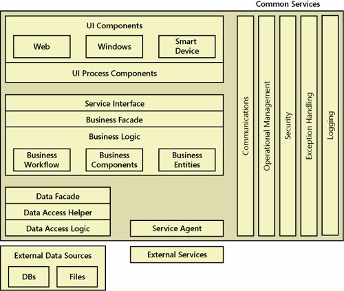 A logical design adds more detail and introduces more models and diagrams (e.g., interaction models, logical object models, logical business services, logical data model, and sequence diagrams). For context, Figure 8-7 provides an example of a sequence diagram. Figure 8-7. Example of a sequence diagram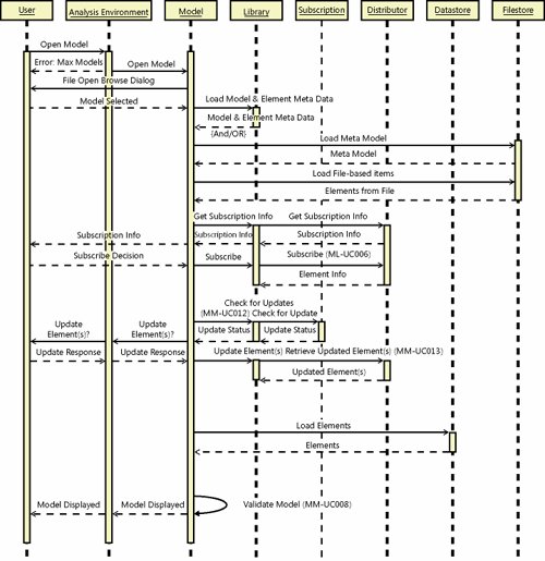 Physical DesignA physical design works through all design details so each subteam is ready to implement a solution and their supporting collateral. The level of details necessary often is based on team member abilities and project constraints. A physical design creates a set of physical solution design models, including components design, user interface design, and physical database design. A physical design addresses other supporting aspects of delivering a solution (e.g., performance testing environment). It explains how a solution integrates and behaves in its target environment. With all design details mapped out, a team should revisit their task and resource estimates. They also should revisit the implementation options outlined previously and select the one that best matches project constraints and how a team wants to implement a solution. Creating a Master Project Plan (Deliverable)Lead Advocacy Group: Program Management
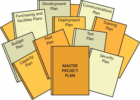
A project plan is a description of how to deliver an aspect of a solution or supporting activity. The various project plans evolve out of strategies and approaches outlined during envisioning. Although some plans are reliant on a solution design, most are not, so planning in parallel with solution designing is recommended. A master project plan, driven by program management, is a reference document that shows how the various project plans synchronize and integrate together. The benefits of presenting these plans as one are that they facilitate synchronization into a single schedule, ensure proper sequencing of activities, facilitate reviews and approvals, and help to identify gaps and inconsistencies. Conversely, the benefits of having a plan made up of smaller plans are that these facilitate concurrent planning by various team advocacy groups and provide for clear accountability because specific advocacy groups are responsible for specific plans. Although a single accountable advocacy group is designated for each plan, planning is a shared responsibility, and every advocacy group is accountable to provide planning input. Plans to be included in a master project plan depend on project characteristics (e.g., type and size). The next few sections identify plans to consider for every project. Obviously, not all are needed for every project. However, their inclusion or exclusion should be considered carefully. Their complexity and depth vary in accordance with delivery challenges. Typical plans included in a master project plan are shown in Figure 8-8. Figure 8-8. Typical plans incorporated into the master project plan Communications PlanLead Advocacy Group: Product Management A Communications Plan maps out how, when, and what information to share with the various stakeholders and with the team. This information can be shared through project deliverables (e.g., end-user e-mail message announcing a solution rollout developed by a user experience team), project events (e.g., training and launch events), project meetings (e.g., monthly project status reports), and approval processes (e.g., business sponsor sign-off of functional specification). Table 8-8 provides a few more examples of external communications.
Roles and ResponsibilitiesLead Advocacy Group: Program Management A Roles And Responsibilities document, sometimes called an organizational plan, details the roles needed on a project; their focus; how they fit into the team structure; and what their responsibilities, competencies, activities, and major deliverables are throughout a solution life cycle. Staffing PlanLead Advocacy Group: Program Management A Staffing Plan describes when and what skills and abilities need to be added to a team to deliver a solution, how to acquire those skills and abilities if they are not readily available, and when and how those resources are rolled off a project team. It identifies how to approach and conduct project orientation for new team members. It details the numbers and types of personnel needed throughout a solution delivery life cycle, as exemplified in Table 8-9.
Readiness PlansLead Advocacy Group: Program Management A Readiness Plan outlines how to approach team readiness and how to implement and manage the MSF Readiness Management Process (discussed in Chapter 7, "MSF Envision Track: Defining a Solution"). Risk and Issue Management PlanLead Advocacy Group: Program Management A Risk And Issue Management Plan outlines how to manage the identification and mitigation of risks and issues. Although risks and issues are managed somewhat differently, the overall approach is consistent with what was discussed in Chapter 5, "Managing Project Risks" (i.e., MSF Risk Management Process). Configuration Management PlanLead Advocacy Group: Program Management As a solution is incrementally built and deployed to the various supporting environments, a Configuration Management Plan details how and which of the various project elements (e.g., deliverables, documents, configurations, and settings) to track. As expressed in Chapter 6, "Establishing a Solution Delivery Life Cycle," configuration management provides controlled deployment and facilitates "rollback" to an earlier configuration of some or all of a solution if needed. Change Management PlanLead Advocacy Group: Program Management A Change Management Plan identifies the goals and approaches of how to handle changes to the agreed-to project scope, cost, time lines, and assigned resources. It delineates the process used to request, review, approve, document, and distribute changes. As with other plans, a team or organization needs to agree and document within this plan how formal the change management process should be. Rigor and formality might be enablers, especially for large teams; however, they come at a cost. Effectively, this plan dictates how a team must behave when looking to alter any feature and functionality of a solution once the solution is placed under change control. This means that features and functions cannot be added or changed without review and approval by both the team and stakeholders. Quality Management PlanLead Advocacy Group: Test A Quality Management Plan details how the quality goals for each advocacy group (discussed in Chapter 4, "Building an MSF Team") will be implemented and measured throughout a solution delivery life cycle. It determines what quality metrics will be used and how they will be measured. Test PlanLead Advocacy Group: Test The basic goals of testing are to find where gaps are between what was built and what was specified (Build Track) and later what was expected (Stabilize Track), and to manage gap remediation. Depending on the selected build methodology and solution delivery technologies (e.g., infrastructure, software development), testing either precedes a build effort (e.g., test-driven development) or follows a build effort. To assemble a testing plan, a team needs to decide how best to approach and implement testing for this project. After all, testing that might be sufficient for one project might not be for another. This involves forming testing strategies and approaches as to how to make sure a solution not only adheres to the requirements (i.e., verification) but also that the requirements delineate what is needed and expected (i.e., validation). Quality bars (i.e., levels of quality) and success criteria need to be set for the various aspects of a solution. Which quality metrics will be used and how they will be measured need to be determined. Specific goals for testing need to be established. The types of tests to be performed need to be identified. Test coverage decisions need to be made. Usage testing needs to be defined. Test collateral (e.g., test cases, test scripts, test harnesses, and test data) needs to be identified and developed prior to a solution being developed. Problem triage strategies and processes need to be defined. Pilot PlanLead Advocacy Group: Product Management A pilot deployment is an opportunity to validate with "real" users that a solution works as expected in a controlled, production-like environment under live conditions. A Pilot Plan defines the strategies, goals, objectives, success criteria, and scope for conducting and assessing the pilot; plans out deployment logistics; and identifies target user populations to participate in the pilot. The plan details how the entire solution will be reviewed and evaluated by the pilot group. Table 8-10 provides some implementation options to consider.
Because the pilot has real users using a solution in real conditions, many production support processes and resources need to be completed in time and be put in place to support these pilot users. For instance, the help desk, user administration, and training need to be ready to support users prior to the start of pilot. Although the pilot can be conducted in a staging environment (i.e., one that mirrors production), it can be hosted in production where resources need to be procured and deployed ahead of the full deployment. All of this can be quite challenging because pilot is usually conducted during a Stabilize Track when most of the team is busy finalizing a solution and getting ready for deployment. Training PlanLead Advocacy Group: User Experience Training has a simple mission: bring user readiness up to the necessary levels. Like the readiness management discipline discussed in Chapter 7, "MSF Envision Track: Defining a Solution," where great planning and effort are expended to ready the team, a Training Plan has the same challenge, but this time it is users that need to be ready. It might even be more challenging because users likely have a broader skills variance. They might also have more varied learning styles. All of this needs to be factored into a Training Plan. A Training Plan also needs to consider training vehicles (e.g., hands-on workshops), availability of users for training (e.g., usually the time needed to properly train far exceeds user availability), and development of training materials. Training logistics need to be planned out (e.g., trainer availability and training facility availability). Table 8-11 provides some implementation options to consider.
Deployment PlanLead Advocacy Group: Release/Operations A team must work through many deployment strategies, approaches, and considerations to have a successful deployment, as exemplified in Table 8-12. A deployment plan documents these, and then identifies how to best deploy all the different aspects of a solution (i.e., different aspects might take different deployment strategies and approaches). It maps out which resources are needed, including people, tools, and scripts. It identifies which solution components are located at a central or key location to enable interoperability of the overall solution (i.e., core components) and which components are located at individual locations (i.e., sites) to enable users to access and use a solution. These components should be grouped for efficient deployment.
Added to this planning is how to promote a solution through the various supporting environments before deploying to production. It also covers how to document the deployed solution (commonly called "as built" documents) to be handed over to operations.
Change Enablement PlanLead Advocacy Group: Product Management The full value of a solution is not often realized without complementary changes to business processes. A Change Enablement Plan addresses how to engage the stakeholders to help make this happen. Knowledge Management PlanLead Advocacy Group: Program Management In support of the MSF foundational principle of learning from all experiences, a Knowledge Management Plan expounds on how to capture and harvest lessons learned while delivering a solution. It details the approaches and processes used. It outlines how to categorize and tag knowledge. It architects the tools and means to manage knowledge. In addition, it discusses how others in an organization will retrieve relevant knowledge. Disaster Recovery PlanLead Advocacy Group: Architecture A Disaster Recovery Plan defines the strategies and important aspects of a solution that warrant disaster recovery for both a delivery effort and for a deployed solution. This plan can be as simple as clustering servers or as elaborate as full alternate sites with near-real-time synchronization. It identifies threats and worst-case scenarios that might significantly affect solution delivery. It provides trade-off analysis to help justify the potentially huge costs of implementing these measures. Purchasing and Facilities PlanLead Advocacy Group: Release/Operations A Purchasing and Facilities Plan, sometimes called a procurement plan, maps out how to acquire the necessary resources to deliver a solution. This includes ordering the hardware, software, and networking equipment for the supporting environments as well as what is required to deploy a solution in production. It sometimes involves securing warehouse space to build and store a solution incrementally as it is deployed globally. It might involve physical plant logistics (e.g., running cables and installing air conditioning), construction logistics (e.g., securing building permits), and disposal of decommissioned equipment. Security PlanLead Advocacy Group: Architecture A Security Plan describes how to identify security requirements, how to adhere to established security guidelines and policies, what actions will be taken to mitigate any risk in the absence of established security guidelines, and what interim security measures will be taken if established security measures conflict with the successful completion of a project. Integration Management PlanLead Advocacy Group: Architecture When there are many disparate aspects of the deployed solution as well as many existing systems to integrate with, effort to draft an Integration Management Plan is often justified. It describes how to integrate the parts of a solution and how to integrate a solution into its destination environment. Benefit Analysis PlanLead Advocacy Group: Product Management Like technical measurement of solution operations, the business value being realized through solution operations can also be measured. The ways and means of approaching and implementing this are detailed in a performance management plan. This plan typically maps out how to track what was presented in the cost/benefit analysis used to justify a project. It can involve tracking cost performance, earned value analysis (EVA), and other less tangible measures of business value. Capacity PlanLead Advocacy Group: Architecture When solution growth is critical, it is best to draft a Capacity Plan. It goes into more detail than what is normally covered within design documents. It forecasts future solution loads, details potential user experience impacts through that growth, and specifies what needs to be incrementally done to a solution and environment (e.g., networks) to handle that planned growth. Budget PlanLead Advocacy Group: Program Management A Budget Plan maps out how to deliver a solution within financial constraints. It instruments how to identify expected costs and cost constraints. It often uses information from the other plans to forecast financial impacts related to their various options and approaches. It paints an overall financial picture. | ||||||||||||||||||||||||||||||||||||||||||||||||||||||||||||||||||||||||||||||||||||||||||||||||||||||||||||||||||||||||||||||||||||||||||||||||||||||||||||||||||||||||||||||||||||||||||||||||||||||||||||||||||||||||||
EAN: 2147483647
Pages: 137