Video Textures
The Ducky sample is interesting, but it has a number of limitations. For one thing, it uses a plain offscreen surface instead of a texture, and there s a limit to what you can do with ordinary surfaces. Textures offer much more interesting possibilities.
A second limitation is that the Ducky sample renders a frame whenever the VMR tells it to, so the frame rate of the 3D scene is driven by the frame rate of the video. In some situations, this may be what you want. Letting the VMR drive the frame rate will certainly produce the smoothest video playback, so for cut scenes that is probably the best approach. However, you might prefer that the sample controls the frame rate instead.
A third limitation is that the Ducky sample uses the VMR in pass-through mode. Pass-through mode has several drawbacks compared with mixing mode. First, there is no video mixing, and the VMR can only render one video stream. Second, you get the video frames exactly as the decoder outputs them, with no massaging by the VMR. For example, there is no automatic deinterlacing. If you watch the Ducky video carefully , you can see horizontal jagged lines ( jaggies ) in the image, especially when the camera pans. This is because the source file is interlaced DV video. The video frames from the decoder contain two fields interleaved together, causing jagged lines in the image. (See the Deinterlacing sidebar.) In mixing mode, the VMR automatically deinterlaces the frame.
The next sample application that we ll describe addresses both of these issues. Run the TeeVee sample that is located in the AVBook\bin directory. This sample renders a 3-D scene of a room with a television set on the floor (see Plate 7). Video plays on the back wall of the room, and the same video plays on the television screen. To achieve this effect, a texture surface is used for the video. When the scene is rendered, the texture is applied twice ” once to the back wall of the room mesh, and once to the television mesh. If you move the camera, you can see that the television screen is convex, causing a slight fish-eye effect. The television screen also has a specular component, which simulates the effect of light reflecting from the glass. These are only some of the possibilities offered by video textures.
A lot of the code in the TeeVee sample is identical to the Ducky sample, so in the following sections we ll focus on the differences.
| |
A television draws an image by moving an electron beam across the surface of the glass. The glass is coated with phosphor, which emits light when struck by the beam. However, the beam does not draw every horizontal scan line on each pass; instead, it skips alternate lines on one pass and draws the missing lines on the next pass. For example, on the first pass it might draw lines 0, 2, 4, 6, and so on. On the next pass it draws lines 1, 3, 5, 7, and so on. Each set of alternating scan lines is called a field. Two fields make up one frame, so the effective frame rate is half the number of fields per second. For example, 60 fields per second gives a frame rate of 30 frames per second. This type of video display, shown in Figure 10.4, is called interlaced video. Analog television broadcasts are one source of interlaced video, and DV camcorders are another.
Unlike television sets, most computer monitors are progressive displays, which means the monitor draws every scan line on each pass instead of skipping lines. To display interlaced video on a progressive monitor, you must deinterlace the video by constructing frames that contain all of the scan lines. The problem is that the second field occurs slightly later than the first field. If there is a lot of motion in the scene, there may be obvious differences between the two fields.
| |
| |
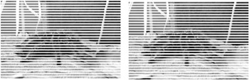
Figure 10.4: Two fields of interlaced video.
The two simplest techniques for deinterlacing video are bob and weave , shown in Figure 10.5. In bob mode, the fields are displayed sequentially. To fill in the missing lines, each scan line is stretched to twice its height. In weave mode, both fields are combined into a single frame by interleaving the scan lines.
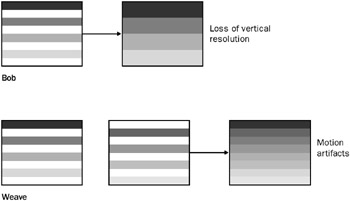
Figure 10.5: Bob and weave modes.
Both techniques have drawbacks. Bob mode reduces the vertical resolution of the image, and weave mode can result in motion artifacts, because two sequential fields are displayed at the same time. More sophisticated deinterlacing techniques use interpolation to fill in the missing information. These techniques can often be implemented very efficiently by the graphics hardware. The DirectShow DV decoder filter outputs each DV frame as two interleaved fields, so in effect, it implements weave mode. When the VMR is in mixing mode, a more advanced deinterlacing technique may be applied before the frame is rendered. (In Chapter 12, we ll see how an application can set deinterlacing preferences.) The Ducky sample uses the VMR in pass-through mode, so the only deinterlacing is the DV decoder s weave, which results in the characteristic jagged lines.
| |
Setting the VMR to Use Mixing Mode
The TeeVee sample uses mixing mode instead of pass-through mode. As we mentioned earlier, pass-through mode is the default setting for the VMR-9 in renderless mode. To enable mixing mode, call IVMRFilterConfig9::SetNumberOfStreams before you connect any of the video streams, and specify the maximum number of video streams that you plan to connect. This value can be 1 if you don t plan to mix multiple streams but still want the VMR to load the compositor. To support mixing mode, the TeeVee sample adds a new member variable, m_dwNumStreams , to the CGraph class. If the value of m_dwNumStreams is more than zero, the InitVMR_RenderlessMode function calls SetNumberOfStreams with the specified value. The new code is shown in bold type.
HRESULT CGraph::InitVMR_RenderlessMode( IVMRSurfaceAllocatorNotify9 **ppAlloc) { .... /* The rest of this function does not change. */ .... if (m_dwNumStreams > 0) { hr = pConfig->SetNumberOfStreams(m_dwNumStreams); } return m_pVMR.QueryInterface(ppAlloc); } The CVmrGame class sets the value of m_dwNumStreams to 1 before calling InitVMR_RenderlessMode .
Restoring the Render Target
In mixing mode, the VMR switches the render target while you re not looking. The reason for this behavior is that the VMR uses Direct3D to composite the video frames onto the back-end surface, and it needs to set this surface as the render target. However, it doesn t restore the original render target when it s done, so we have to restore it before we draw our scene.
In the CAllocator::SetDevice method, we call IDirect3DDevice9::GetRenderTarget to get a pointer to the current render target, and we store this pointer in a new member variable, m_pRenderTarget . (Recall that SetDevice is a custom method on our allocator-presenter, and is not part of the COM interfaces.) Here is the new code.
HRESULT CAllocator::SetDevice(IDirect3DDevice9 *pDevice) { if (!pDevice) { return E_POINTER; } m_pDevice = pDevice; m_pRenderTarget.Release(); // Release the old pointer, if any. m_pDevice->GetRenderTarget(0, &m_pRenderTarget); return S_OK; } Now we can restore the render target in the PresentImage method:
STDMETHODIMP CAllocator::PresentImage(DWORD_PTR dwUserID, VMR9PresentationInfo* pPresInfo) { CLock lock(&m_CritSec); // Restore the original render target. m_pDevice->SetRenderTarget(0, m_pRenderTarget); .... return hr; } Creating a Texture Surface
To create a texture surface in the InitializeDevice method, we add the VMR9AllocFlag_TextureSurface flag to the dwFlags field in the VMR9AllocationInfo structure. Also, we get rid of the code from the Ducky sample that calls CheckDeviceFormatConversion , which was needed to test for StretchRect support. The new code is shown in bold.
STDMETHODIMP CAllocator::InitializeDevice(DWORD_PTR dwUserID, VMR9AllocationInfo* pAllocInfo, DWORD* pNumBuffers) { CLock lock(&m_CritSec); if (!pAllocInfo !pNumBuffers) { return E_POINTER; } // We want a texture surface. pAllocInfo->dwFlags = VMR9AllocFlag_TextureSurface; .... // Create the array of surface pointers, and allocate the surfaces. // This code is identical to the Ducky sample. } Not all video drivers support texture surfaces with non-power-of-2 sizes. For now, we ll simply gloss over this issue and assume that the video driver supports them. However, this is a complication that we do need to consider, and we ll come back to it at the end of this chapter.
Rendering the Scene
When it is time to render a frame, the VMR calls PresentImage . First we restore the render target, as shown earlier. Then we retrieve a pointer to the surface s texture by calling IDirect3DSurface9::GetContainer . (The VMR always gives us a pointer to the surface, not the texture.) The CVmrGame class will use this texture when it renders the scene.
STDMETHODIMP CAllocator::PresentImage(DWORD_PTR dwUserID, VMR9PresentationInfo* pPresInfo) { CLock lock(&m_CritSec); // Restore the original render target. m_pDevice->SetRenderTarget(0, m_pRenderTarget ); // Get the parent texture from the surface pointer. pPresInfo->lpSurf->GetContainer(IID_IDirect3DTexture9, (void**)&m_pVideoTex); // Render the frame. m_pGame->DoGameLoop(); // Release the texture. m_pVideoTex.Release(); return S_OK; } Some changes are also needed in the code that renders the scene. Obviously, the scene objects themselves are different, as reflected in how the CMyScene class loads the meshes. But we also need to associate the video texture surface with the scene objects. Here is the new code.
HRESULT CVmrGame::Render() { // Restore rendering settings that the VMR may have changed. RestoreRenderSettings(); m_Device.Clear(0x00); HRESULT hr = m_pDevice->BeginScene(); if (FAILED(hr)) { return hr; } // Get the video texture pointer from the allocator. IDirect3DTexture9 *pTex = m_pAlloc->m_pVideoTex; if (m_pScene) { // Set the video texture on the scene meshes. CMesh *p1 = m_pScene->m_MeshList[ROOM_MESH]; CMesh *p2 = m_pScene->m_MeshList[TV_MESH]; p1->SetTexture(ROOM_MESH_BACKWALL, pTex); p2->SetTexture(TV_MESH_SCREEN, pTex); m_pScene->Render(m_pDevice); // Render the scene meshes. // Clear the texture, because pTex will become invalid // after this method returns. p1->SetTexture(ROOM_MESH_BACKWALL, NULL); p2->SetTexture(TV_MESH_SCREEN, NULL); } m_pDevice->EndScene(); hr = m_pDevice->Present(NULL, NULL, NULL, NULL); return hr; } The RestoreRenderSettings method restores some render settings that the VMR may have changed when it mixed the video. We ll explain that code in a moment. Next, we call a method on our custom CMesh class to associate the video texture with a particular subset of the mesh, overriding whatever texture was defined in the original model. For the TeeVee sample, we place the video texture on the back wall of the room and on the television screen. The indices of the mesh subsets are hard-coded using define constants, based on the models that we loaded. Here is the code for the CMesh::SetTexture method.
HRESULT CMesh::SetTexure(DWORD iSubset, IDirect3DTexture9 *pTexture) { if (iSubset >= m_dwNumMaterials) { return E_INVALIDARG; } SAFE_RELEASE(m_ppTextures[iSubset]); m_ppTextures[iSubset] = pTexture; if (pTexture) { pTexture->AddRef(); } return S_OK; } Switching textures is relatively costly in the rendering pipeline, so a good optimization is to sort your meshes by texture ” unlike the code here, which was designed mainly for ease of implementation.
VMR Render States in Mixing Mode
In mixing mode, the VMR changes some of the Direct3D render states so that it can mix the video streams onto the back-end surface. Therefore, we set them back in the RestoreRenderSettings function. Of course, your own application may use different settings than the ones shown here.
void CVmrGame::RestoreRenderSettings() { m_pDevice->SetRenderState(D3DRS_CULLMODE, D3DCULL_CCW); m_pDevice->SetRenderState(D3DRS_LIGHTING, TRUE); m_pDevice->SetRenderState(D3DRS_AMBIENT, m_AmbientLightColor); m_pDevice->SetRenderState(D3DRS_ALPHABLENDENABLE, FALSE); m_pDevice->SetRenderState(D3DRS_ALPHATESTENABLE, FALSE); m_pDevice->SetRenderState(D3DRS_SRCBLEND, D3DBLEND_ONE); m_pDevice->SetRenderState(D3DRS_DESTBLEND, D3DBLEND_ZERO); m_pDevice->SetTextureStageState(0, D3DTSS_COLOROP, D3DTOP_MODULATE); m_pDevice->SetTextureStageState(0, D3DTSS_COLORARG1, D3DTA_TEXTURE); m_pDevice->SetTextureStageState(0, D3DTSS_COLORARG2, D3DTA_CURRENT); m_pDevice->SetSamplerState(0, D3DSAMP_ADDRESSU, D3DTADDRESS_CLAMP); m_pDevice->SetSamplerState(0, D3DSAMP_ADDRESSV, D3DTADDRESS_CLAMP); m_pDevice->SetSamplerState(0, D3DSAMP_MAGFILTER, D3DTEXF_LINEAR); m_pDevice->SetSamplerState(0, D3DSAMP_MINFILTER, D3DTEXF_LINEAR); m_pDevice->SetSamplerState(0, D3DSAMP_MIPFILTER, D3DTEXF_LINEAR); } The following tables list the settings that the VMR uses in mixing mode.
| Render state | Setting | Description |
|---|---|---|
| D3DRS_CULLMODE | D3DCULL_NONE | Do not cull back faces. |
| D3DRS_LIGHTING | FALSE | Disable lighting. |
| D3DRS_ALPHABLENDENABLE | TRUE | Enable alpha blending. |
| D3DRS_SRCBLEND | D3DBLEND_SRCALPHA | Blend the source s alpha value. |
| D3DRS_DESTBLEND | D3DBLEND_INVSRCALPHA | Blend the inverse of the destination s alpha value (1 - alpha). |
| Texture stage 0 | Setting | Description |
|---|---|---|
| D3DTSS_COLOROP | D3DTOP_SELECTARG1 | Use the first color argument, unmodulated. |
| D3DTSS_COLORARG1 | D3DTA_TEXTURE | Use the texture color. |
| D3DTSS_ALPHAARG1 | D3DTA_DIFFUSE | Use the diffuse vertex color for the alpha. |
| Sampler state | Setting | Description |
|---|---|---|
| D3DSAMP_ADDRESSU | D3DTADDRESS_CLAMP | Clamp texture along the u-axis. |
| D3DSAMP_ADDRESSV | D3DTADDRESS_CLAMP | Clamp texture along the v-axis. |
| D3DSAMP_MAGFILTER | Depends on the value set in IVMRMixerControl9::SetMixingPrefs . Defaults to point filtering (D3DTEXF_POINT). | |
| D3DSAMP_MINFILTER | ||
| D3DSAMP_MIPFILTER |
The flexible vertex format (FVF) is set to D3DFVF_XYZRHW D3DFVF_DIFFUSE D3DFVF_TEX1 . The diffuse vertex color is white (0xFFFFFF) and lighting is disabled, so no Gouraud shading is performed on the pixels in the frame.
For each stream, if the media type has a valid alpha channel (which is not common), the VMR sets the following render states.
| Render state | Setting | Description |
|---|---|---|
| D3DRS_ALPHATESTENABLE | TRUE | Enable per-pixel alpha testing. |
| D3DRS_ALPHAFUNC | D3DCMP_GREATER | Write only pixels that exceed the reference alpha. |
| D3DRS_ALPHAREF | 0x10 | Reference alpha. |
| Texture stage 0 | Setting | Description |
|---|---|---|
| D3DTSS_ALPHAOP | D3DTOP_MODULATE | Modulate the two alpha arguments. |
| D3DTSS_ALPHAARG1 | D3DTA_TEXTURE | Use the texture color for argument 1. |
| D3DTSS_ALPHAARG2 | D3DTA_DIFFUSE | Use the diffuse vertex color for argument 2. |
These settings enable per-pixel alpha testing. Otherwise, if the media type does not contain a valid alpha channel, the VMR sets the following values.
| Render state | Setting | Description |
|---|---|---|
| D3DRS_ALPHATESTENABLE | FALSE | Disable per-pixel alpha testing. |
| Texture stage 0 | Setting | Description |
|---|---|---|
| D3DTSS_ALPHAOP | D3DTOP_SELECTARG1 | Use the first alpha argument, unmodulated. |
| D3DTSS_ALPHAARG1 | D3DTA_DIFFUSE | Use the diffuse vertex color. |
Note that even when the incoming video does not contain alpha information, the video frame as a whole may have an alpha value set by the sample application, as part of the mixing preferences.
Handling Non-Power-of-2 Textures
The graphics driver may not support textures with non-power-of-2 dimensions. The dimensions of your video source are not likely to be even powers of 2, so if the driver requires power-of-2 textures, we need to adjust the size of the texture inside the InitializeDevice method.
To check for driver support, call IDirect3DDevice9::GetDeviceCaps and examine the TextureCaps field. The D3DPTEXTURECAPS_POW2 flag means the driver does not provide general support for non-power-of-2 textures. This flag might be combined with the D3DPTEXTURECAPS_NONPOW2CONDITIONAL flag, which means the driver supports certain kinds of non-power-of-2 textures, but with various restrictions. Depending on your sample application, you may want to check for that flag or simply ignore it. (In our experience, it s safer to ignore the flag and always create power-of-2 textures if the D3DPTEXTURECAPS_POW2 flag is present.) Also check for the D3DPTEXTURECAPS_SQUAREONLY flag, which means the driver requires square textures.
If you determine that a power-of-2 texture is required, simply scale up the width and height to the next power of 2 before calling AllocateSurfaceHelper . If a square texture is required, take the maximum of both dimensions. To handle these various permutations , the TeeVee sample adds the following helper function, AdjustTextureSize , to the CAllocator class.
void CAllocator::AdjustTextureSize(VMR9AllocationInfo* pAllocInfo) { D3DCAPS9 caps; m_pDevice->GetDeviceCaps( &caps ); if (caps.TextureCaps & D3DPTEXTURECAPS_POW2) { DWORD dwWidth = 1; DWORD dwHeight = 1; // Multiply each dimension by 2 until it is large enough. while( dwWidth < pAllocInfo->dwWidth ) { dwWidth = dwWidth << 1; } while( dwHeight < pAllocInfo->dwHeight ) { dwHeight = dwHeight << 1; } // Check whether square textures are required. if (caps.TextureCaps & D3DPTEXTURECAPS_SQUAREONLY) { dwHeight = dwWidth = max(dwWidth, dwHeight); } // Calculate the scaling factor for the texel coordinates. m_fTU = (float)(pAllocInfo->dwWidth) / (float)(dwWidth); m_fTV = (float)(pAllocInfo->dwHeight) / (float)(dwHeight); // Set the new dimensions. pAllocInfo->dwWidth = dwWidth; pAllocInfo->dwHeight = dwHeight; } } If the texture surface is scaled up, you don t want the extra area of the texture to show. (It will be filled with the background color specified by the mixing preferences of the application, with black as the default color.) The m_fTU and m_fTV variables in the AdjustTextureSize function are used to calculate a scaling factor for the texels in each dimension. Both variables are initialized to 1.0, so if the driver does support non-power-of-2 textures, the entire texture is applied to the model. Otherwise, a smaller portion of the texture is applied. The following function sets the appropriate scaling transform on the first texture stage.
HRESULT CAllocator::ScaleVideoTexture() { CLock lock(&m_CritSec); HRESULT hr = S_OK; if ((m_fTU != 1.0f) (m_fTV != 1.0f)) { D3DXMATRIX mat; D3DXMatrixIdentity(&mat); D3DXMatrixScaling(&mat, m_fTU, m_fTV, 1.0f); hr = m_pDevice->SetTransform(D3DTS_TEXTURE0, &mat); if (SUCCEEDED(hr)) { hr = m_pDevice->SetTextureStageState(0, D3DTSS_TEXTURETRANSFORMFLAGS, D3DTTFF_COUNT2); } } return hr; } In the TeeVee sample, the other textures in the scene are just patterns, so it doesn t matter if they get scaled. Therefore, we just call ScaleVideoTexture once, and the same texture transform remains in place throughout the rendering process. With more complicated models, you probably want to remove the scaling transform when you apply the other textures in the scene, or else use two texture stages.
Oversized Textures
If the video image is larger than the back buffer, Direct3D will complain (via the debug output) that your depth-stencil buffer is smaller than your render target, and it won t render the video.
This is unlikely to happen in full-screen mode. But suppose your application renders DV video (640 x 480) in windowed mode, using power-of-2 textures. The resulting video texture will be 1024 x 512 pixels, which could easily be larger than the application window. In that case, you need to replace the default depth buffer with a larger one. (This assumes that you set EnableAutoDepthStencil to TRUE when you first created the Direct3D device.) Create a new depth buffer by calling IDirect3DDevice9::CreateDepthStencilSurface . Then call IDirect3DDevice9::SetDepthStencilSurface to set the new buffer. The CAllocator::FixDepthBuffer function encapsulates this process.
HRESULT CAllocator::FixDepthBuffer(VMR9Alloca tionInfo* pAllocInfo) { // Private method. The caller should hold the critical section. HRESULT hr = S_OK; // Check if the video size is larger than the back buffer. if ((pAllocInfo->dwWidth > m_pGame->m_Device.GetWidth()) (pAllocInfo->dwHeight > m_pGame->m_Device.GetHeight())) { // Create a new depth buffer. CComPtr<IDirect3DSurface9> pDepth; hr = m_pDevice->CreateDepthStencilSurface( pAllocInfo->dwWidth, // Width pAllocInfo->dwHeight, // Height m_pGame->m_Device.GetDepthStencilFormat(), // Same format. D3DMULTISAMPLE_NONE, // No multisampling 0, // Multisample quality FALSE, // Disable z-buffer discarding. &pDepth, NULL); if (SUCCEEDED(hr)) { hr = m_pDevice->SetDepthStencilSurface(pDepth); } } return hr; } Frame Stepping
We mentioned earlier that you might want the application, rather than the VMR, to control the frame rate. Unfortunately there s no elegant solution to this problem. The fundamental difficulty is that DirectShow works on a push model ” the AVI Splitter filter pushes samples to the decoder as quickly as possible, and the VMR controls the flow of data by holding frames until it is time for them to be rendered. Ideally, we would want a pull model, in which the application requests frames one at a time. DirectShow does not provide this ability directly, but we can get almost the same effect by using a technique called frame stepping . Frame stepping enables the VMR to step through the video one frame at a time.
First, we must deactivate the filter graph s clock. Normally, the Filter Graph Manager automatically selects a clock for the entire graph, called the reference clock . The reference clock enables the renderer filters to schedule when they render samples, based on the presentation time of each sample. It is also used to keep audio and video streams in sync. Because we re using frame stepping, we don t want the VMR to schedule the rendering. Therefore, we disable the reference clock by calling the Filter Graph Manager s IMFMediaFilter::SetSyncSource method with the value NULL .
CComQIPtr<IMediaFilter> pMF(m_pGraph); pMF->SetSyncSource(NULL);
Next, instead of running the filter graph by calling Run , we call IVideoFrameStep::Step to step forward by one frame.
CComPtr<IVideoFrameStep> m_pFrameStep; m_pGraph.QueryInterface(&m_pFrameStep); hr = m_pFrameStep->CanStep(1, NULL); if (SUCCEEDED(hr)) { m_pFrameStep->Step(1, NULL); } The IVideoFrameStep interface is exposed by the Filter Graph Manager, but the frame-stepping mechanism is implemented, in this case, by the VMR filter. If no filter in the graph supports frame stepping, the CanStep method returns an error code. That shouldn t happen, because we know that the VMR supports frame stepping, but it doesn t hurt to check. The first parameter to the Step and CanStep methods is the number of frames to step. For example, you could step forward 2 frames at a time, skipping every other frame. Even if you skip frames, however, the decoder still decodes the frames that you skip, because the VMR is doing the stepping, not the decoder. (In any case, with many kinds of video compression, it is not possible for the decoder to skip frames arbitrarily, because the previous frames are needed to decode the current frame.)
The Step method is asynchronous, so it returns immediately. When the VMR has a new frame ready, it calls the Present method of the allocator-presenter on the DirectShow streaming thread, as before. When the frame has been rendered, the Filter Graph Manager sends an EC_STEP_COMPLETE event to the application. This signals that you can call Step again to step forward another frame. We add this logic to the event handling code in the CVmrGame class.
void CVmrGame::OnGraphEvent(long lEvent, long lParam1, long lParam2) { if (lEvent == EC_STEP_COMPLETE) { m_Graph.FrameStep(); } else if (lEvent == EC_COMPLETE) { m_Graph.Stop(); m_Graph.Seek(0); m_Graph.FrameStep(); } } Now the graph will run as fast as the decoder can run, or as fast as the application allows. If you set the Direct3D presentation interval to D3DPRESENT_INTERVAL_DEFAULT , rendering will also be gated by the monitor refresh rate.
Using Surface Copies for Independent Frame Rates
We ve shown two different ways to get video frames from the VMR. In the Ducky sample, the video is rendered on a DirectShow streaming thread and the VMR tells the sample when to present a new frame. In the TeeVee sample, the sample requests a new frame and the VMR notifies it when the frame is available. In both cases, the 3-D scene is drawn once for every video frame. A third option is to make a private copy of the video frame and always draw from the private copy. With this approach, you can draw the 3-D scene at any frame rate, independent of the video frame rate. Just make sure to hold a critical section for any code paths that access the surface. The drawback is the extra copy required. Also, this approach can only work in pass-through mode. In mixing mode, the VMR uses the Direct3D device to composite the video. As a result, the only time it s safe for the application to make BeginScene and EndScene calls is inside the PresentImage method of the allocator-presenter.
EAN: 2147483647
Pages: 120