Warm Reset
| Warm reset can be triggered by a hardware event, or system software may initiate a warm reset. Note that the system must not generate a warm reset when changing the frequency or width of a link. Specifically, if one side of the link has had its width or frequency changed, but not the other side, following warm reset, one side of the link would think the other is faster and/or wider than what it is actually programmed to be. Warm reset is detected when PWROK is asserted (logic high) and RESET# is asserted (logic low). Warm reset differs from a cold reset in following ways:
Table 12-6 lists the state of the HT signals during a warm reset. Table 12-6. Signal States During Warm Reset
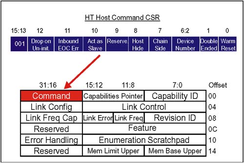
Following warm reset the same synchronization sequence (i.e. same as cold reset) is performed to initialize the transmit and receive clocks. Warm Reset Generated by SoftwareThe specification defines a bit in the HT bridge's HyperTransport Host Command CSR that provides a way for software to initiate warm reset on the secondary bus of an HT-to-HT bridge. Refer to Figure 12-20 on page 304. Specifically, this bit defines the type of reset that will be initiated on the secondary bus when software sets the Secondary Bus Reset bit of the Bridge Control register. Figure 12-20. HyperTransport Host Command CSR The state of the warm reset bit only has meaning when software initiates a reset sequence. Actions taken during the reset sequence depends on the state of the warm reset bit as follows :
It is the responsibility of the hardware to sequence PWROK and RESET# correctly. Changing the state of the Warm Reset bit while the Secondary Bus Reset bit is asserted results in undefined behavior. Defined changes include:
RESET# must be asserted for at least 1ms during a warm reset sequence. |
EAN: 2147483647
Pages: 182