| The following three diagrams and associated descriptions explain the initialization of HyperTransport buffer counts, followed by the actions taken by the transmitter and receiver as two packets are sent across the link. The diagrams have been simplified to show a single flow control buffer and the corresponding receiver and transmitter counters used to track available entries. In this example, assume the following: -
The flow control buffer illustrated is the Posted Request Command (CMD) buffer. -
The designer of the receiver interface has decided to construct this flow control buffer with a depth of five entries. Because this is a buffer for receiving requests , each entry in the buffer will hold up to 8 bytes (this covers the case of either four or eight byte request packets) -
Following initialization, the transmitter wishes to send two Posted Request packets to the receiver. Basic Steps In Counter Initialization And Use -
At reset, the transmitter counters in each device are reset = 0. This prevents the initiation of any packet transfers until buffer depth has been established. -
At reset, the receiver interfaces load each of the RCV counters with a value that indicates how many entries its corresponding flow control buffer supports (shown as N in the diagram). This is necessary because the receiver is allowed to implement buffers of any depth. -
Each device then transmits its initial receiver buffer depth information to the other device using NOP packets. Each NOP packet can indicate a range of 0-3 entries. If the receiver buffer being reported is deeper than 3 entries, the device will send additional NOPs which carry the remainder of the count. -
As each device receives the initial NOP information, it updates its transmitter flow control counters, adding the value indicated in the NOP fields to the appropriate counter total. -
When a device has a non-zero value in the counter, it can send packets of the appropriate type across the link. Each time it sends packet(s), the device subtracts the number of packets sent from the current transmitter counter value. If the counter decrements to 0, the transmitter must wait for NOP updates before proceeding with any more packet transmission. Initializing The Flow Control Counter In Figure 5-4 on page 111, assume that the designer of Device 2 has implemented a Posted Request (CMD) buffer with a depth of 5 entries. After reset, it must convey this initial buffer availability to the transmitter in the other device before any Posted Request packets may be sent. Figure 5-4. Flow Control Counter Initialization 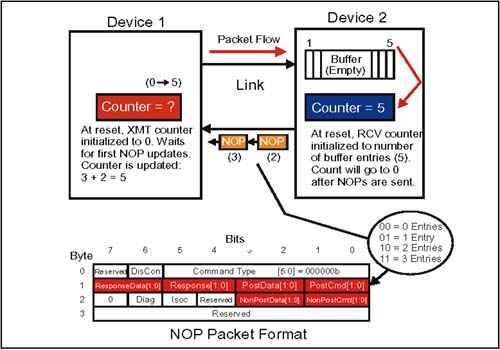 The basic steps in flow control counter initialization are: -
The transmitter in Device 1 initializes its Posted Request (CMD) counter to 0 at reset (all transmit counters reset = 0). It then waits for the receiver on the other side to update this counter with the starting buffer depth available (this will be the maximum depth the receiver supports). -
Device 2 loads its receiver Posted Request counter = 5 (its maximum). -
Device 2 then sends two NOP packets which carry this buffer availability information: the first NOP has a 11b (3) in the Post CMD field (Byte 1, bits 0,1 above), and the second NOP has a 10b (2) in this field. Total = 5. -
Upon receipt of these two NOPs, the Device 1 has updated its transmit counter, first by three then again by two. It now has 5 "credits" available for sending Posted Request packets representing five separate Posted Requests which may be initiated. -
Having sent the NOPs, the Device 2 RCV counter is now at 0, and will remain that way until additional packets are received, processed , and move out of the buffer, thereby creating new entries. Note that this process will be repeated for each of the six required flow control buffers; it will also be done for the six isochronous flow control buffers if they are supported. In the NOP packet format (see above), six transmit registers can be updated at once using the six fields provided. The Isoc bit (Byte 2, bit 5) would be set if the NOP update was to be applied to the isochronous flow control buffer set. Device 1 Sends Two Posted Request Packets Figure 5-5 on page 113 shows the Device 1 transmitter sending two Posted Request packets. Also illustrated is the state of the flow control registers after this has been done, but before the receiver has processed the incoming packets. Figure 5-5. Device 1 Sends Two Packets 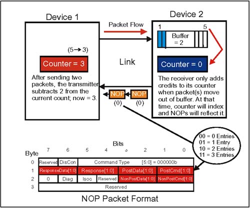 What the diagram shows: -
After the flow control counters are initialized after reset, the transmitter sends packets for which credits are available in the transmit counter, then subtracts the number of packets sent from the current total. In this case, two credits were subtracted from the starting count of 5. Maintaining its own counter assures the transmitter will never send packets which can't be taken, even if there is a considerable lag in NOP updates from the receiver. -
The receiver will not update its RCV counter or indicate new entries in its NOP packets until it moves a packet out of the flow control buffer. New Entries Available: Update Flow Control Information The last diagram, Figure 5-6 on page 114, shows the updating of flow control information after the receiver has processed the two packets it received previously. These could have been consumed internally, or been forwarded to another link if Device 2 is a bridge or tunnel. Figure 5-6. Device 2 Updates Flow Control Information 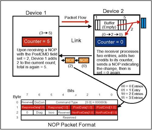 What has happened : -
When Device 2 moves packets out of its buffer, it indexes its receive counter to reflect the new availability (2), and sends this information to Device 1 with a NOP update packet carrying the value 2 in the PostCMD field. After sending the update NOP, Device 2 clears its receive counter. -
After sending packets and subtracting credits from its transmit counter, Device 1 will parse incoming NOPs for updates from the receiver enabling it to bump credits in one or more of its counters. In this case, Device 1 bumps its transmit counter by 2 upon receiving the NOP update. It again has 5 credits to use for sending Posted Request command packets. This dynamic updating of flow control information happens continuously during idle times on the bus. If the receiver has no change in buffer entry availability to report, the NOPs it sends will have all six fields in the NOP packet cleared.  |