Flow Control Buffer Arrangement
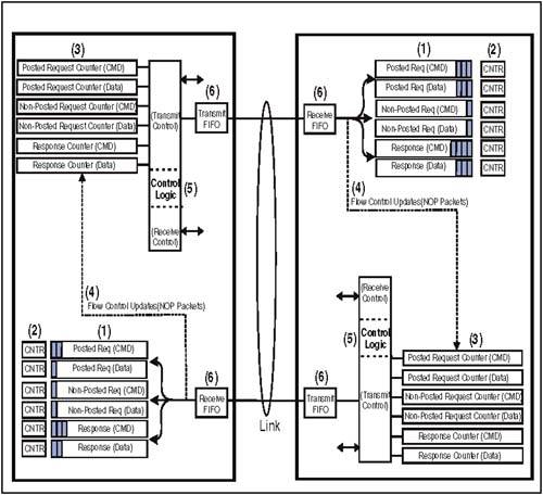
| Figure 5-3 on page 107 illustrates the general arrangement of HyperTransport flow control buffers and counters required of each link receiver interface. Note that while the transmit interface maintains flow control counters, the flow control buffers are only on the receive side of each device. Figure 5-3. Flow Control Buffers And Counters Details Associated With Figure 5-3The following section describes the architectural features shown in Figure 5-3 on page 107. Note that the drawing is conceptual and is intended to show the major features of flow control on a single link. For multiple-link devices such as tunnels, this logic would be replicated for each interface. Flow Control Buffer Pairs (Item 1)Each receiver interface is required to implement six buffers to accept the following packet types being sent by the corresponding transmitter. The specification requires a minimum depth of one for each buffer, meaning that a receiver is permitted to deal with as few as one packet of each type at a time. It may optionally increase the depth of one or more of the buffers to track multiple packets at a time. Posted Request Buffer (Command)This buffer stores incoming posted request packets. Because every request packet is either four or eight bytes in length, each entry in this buffer should be eight bytes deep. Posted Request Buffer (Data)This buffer is used in conjunction with the previous one and stores data associated with a Posted Request. Because posted request data packets may range in size from 1 dword to 16 dwords (64 bytes), each entry in this buffer should be 64 bytes deep. Non-Posted Request Buffer (Command)This buffer stores incoming non-posted request packets. Because every request packet is either four or eight bytes in length, each entry in this buffer should be eight bytes deep. Non-Posted Request Buffer (Data)This buffer is used in conjunction with the previous one and stores data associated with a Non-Posted Request. Because non-posted request data packets may range in size from 1 dword to 16 dwords (64 bytes), each entry in this buffer should be 64 bytes deep. Response Buffer (Command)This buffer stores returning response packets. Because every response packet is four bytes in length, each entry in this buffer should be four bytes deep. Response Buffer (Data)This buffer is used in conjunction with the previous one and stores data associated with a returning response. Because responses may precede data packets ranging in size from 1 dword to 16 dwords (64 bytes), each entry in this buffer should be 64 bytes deep. Receiver Flow Control Counters (Item 2)The receiver interface uses one counter for each of the flow control buffers to track the availability of new buffer entries. The size of the counter is a function of how many entries were designed into the corresponding flow control buffer. After initialization reports the starting buffer size to the transmnitter, the value in each counter only increments when a new entry becomes available due to a packet being consumed or forwarded; it decrements when NOP packets carrying buffer update information are sent to the transmitter on the other side of the link. Transmitter Flow Control Counters (Item 3)It is a transmitter responsibility on each link to check the current state of receiver readiness before sending a packet in any of the three required virtual channels. It does this by maintaining its own set of flow control counters, which track the available entries in the corresponding receiver flow control buffer. For example, if the transmitter wishes to send a read request across the link, it would first consult the Non-Posted Request CMD counter to see the current number of credits. If the counter = 0, the receiver is not prepared to accept any additional packets of this type and the transmitter must wait until the count is updated via the NOP mechanism to a value >0. If the counter value is =1, the receiver will accept one packet of this type, etc. Note that for requests that are accompanied by data (e.g. posted or non-posted writes ), the transmitter must consult both its CMD counter and the Data counter for that virtual channel. If either is at 0, it must wait until both counters have been updated to non-zero values. NOP Packet Update Information (Item 4)During idle times on the link, each device sends NOP packets to the other. If one or more buffer entries in any of the six receiver flow control buffers have become available, designated fields in the NOP packets are encoded to indicate that fact. Otherwise those fields contain 0, indicating no new buffer entries have become available since the previous NOP transmission. In the next section, use of the NOP packet fields for flow control updates is reviewed. Refer to "NOP Packet" on page 71 for additional discussion of the NOP packet format. Control Logic (Item 5)This generic representation of internal control logic is intended to indicate that a number of things related to flow control are under the management of each HyperTransport device. In general:
Transmit AndReceive FIFO (Item 6)The transmit and receive FIFOs are not part of flow control at all, and are shown here as a reminder that all packets moving across the high-speed HyperTransport link pass through an additional layer of buffering to help deal with the effects of clock mismatch within the two devices, skew between multiple clocks sourced by the transmitter on a wide interface, etc. See Chapter 15, entitled "Clocking," on page 387 for a discussion concerning the FIFOs. |
EAN: 2147483647
Pages: 182