| Table 4-1 on page 69 summarizes the HyperTransport Information, Request, and Response control packet types and the command names associated with them. Some things to note in the table: -
For each packet variant, the virtual channel (VChan) is indicated in the second column: posted, non-posted , or response. Note: information packets do not travel in any of the virtual channels and are not subject to flow control. -
The first byte in each control packet type contains a 6-bit Command (CMD) Code. By sending this information at the beginning of a control packet, the receiver is informed immediately of the type of packet being transferred, the number of bytes to expect, and the format of the bit fields contained within. The Command Codes are shown in the left column of Table 4-1. -
In some Command Codes, a number of bits are variables (indicated by ".xxx") which are used to select transaction options: dword vs. byte transfer count, isochronous flag, coherency requirement, etc.; refer to the Comments column Table 4-1 for usage of each optional bit. Table 4-1. Control Packets And The HyperTransport Command Types | CMD Code | V Chan | Command Name | Packet Type | Comments | | 000000 | ----- | NOP | Info | Used by each receiver to report flow-control information to its transmitter. | | 111111 | ----- | Sync/Error | Info | Similar to PCI SERR#, indicates need for link reset and re-synchronization. | | 101xxx | Posted | Sized Write (Posted) | Request | Usage of three least-significant bits: [2] Dword/Byte (1 = dword; 0 = byte). [1] Isoc request (1 = Isoc; 0 = std.). [0] Coherency (1 = req'd; 0 = not) | | 001xxx | Non-Posted | Sized Write (Non-Posted) | Request | Usage of three least-significant bits: [2] Dword/Byte (1 = dword; 0 = byte). [1] Isoc request (1 = Isoc; 0 = std.). [0] Coherency (1 = req'd; 0 = not) | | 111010 | Posted | Broadcast Message | Request | Broadcast messages originate at host bridge, and are accepted and propagated downstream by all devices which see them. | | 01xxxx | Non-Posted | Sized Read (all reads are non-posted) | Request | Usage of four least-significant bits: [3] Response may pass posted requests (1 = OK; 0 = Do not pass) [2] Dword/Byte (1 = dword; 0 = byte). [1] Isoc(1 = Isochronous; 0 = std.). [0] Coherency (1 = req'd; 0 = not) | | 000010 | Non-Posted | Flush | Request | Forces all preceding posted writes in same transaction stream to destination (within host). | | 111100 | Posted | Fence | Request | Forces all preceding posted writes to destination (all virtual channels). | | 111101 | Non-Posted | Atomic RMW | Request | A non-posted write transaction with a read response. Two variants: Fetch and Add, Compare and Swap. Both variants allow reading, modification, and write back of a "locked" memory location semaphore. | | 110000 | Resp | Read Response | Response | On read and Atomic RMW transactions, read response precedes the data being returned by target. In the event of a failure in completing the read, error bits in the response indicate the nature of the problem. | | 110011 | Resp | Target Done | Response | On non-posted write or flush transactions, target done response confirms completion. In the event of a failure, error bits in the response indicate the nature of the problem. | Control Packets: Information There are two types of Information control packets, NOP and Sync/Error. These four-byte packets are exchanged between the transmitter-receiver pairs on a single link. Unlike request and response packets, information packets are not flow controlled; when one is sent by a transmitter to its corresponding receiver, it must be accepted. NOP Packet The NOP (No Operation) command indicates an idle condition on the link. After the link is initialized , each transmitter issues NOP commands continuously unless another command type is required. In addition to indicating the idle condition, these packets inform the device receiving them about changes in the status of flow control buffers and other miscellaneous information concerning link management and diagnostics. Figure 4-6 on page 71 depicts the various fields of the four-byte NOP packet. Table 4-2 immediately following summarizes the usage of each bit field. Figure 4-6. Control Packets: NOP Information 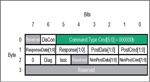 Table 4-2. HyperTransport NOP Packet Bit Assignments | Byte | Bit | Function | | | 5:0 | NOP Command Code . This is the six bit command code for a NOP information packet. Value = 000000b. | | | 6 | DisCon . When this bit is set to a one, the transmitter is indicating that it is starting a LDTSTOP# disconnect sequence. All six buffer release fields must all be = 0 when this bit is set (see next two bytes in packet format). | | | 7 | Reserved . Tie to low level. | | 1 | 1:0 | PostCmd[1:0]. Number of posted command buffer entries released since last NOP. Two bit field is coded as: 00 = 0 posted command buffer entries released since last NOP 01 = 1 posted command buffer entry released since last NOP 10 = 2 posted command buffer entries released since last NOP 11 = 3 posted command buffer entries released since last NOP | | 1 | 3:2 | PostData[1:0]. Number of posted data buffer entries released since last NOP. Two bit field is coded as: 00 = 0 posted data buffer entries released since last NOP 01 = 1 posted data buffer entry released since last NOP 10 = 2 posted data buffer entries released since last NOP 11 = 3 posted data buffer entries released since last NOP | | 1 | 5:4 | Response[1:0]. Number of response command buffer entries released since last NOP. Two bit field is coded as: 00 = 0 response buffer entries released since last NOP 01 = 1 response buffer entry released since last NOP 10 = 2 response buffer entries released since last NOP 11 = 3 response buffer entries released since last NOP | | 1 | 7:6 | ResponseData[1:0]. Number of response data buffer entries released since last NOP. Two bit field is coded as: 00 = 0 response data buffer entries released since last NOP 01 = 1 response data buffer entry released since last NOP 10 = 2 response data buffer entries released since last NOP 11 = 3 response data buffer entries released since last NOP | | 2 | 1:0 | NonPostCmd[1:0]. Number of non-posted command buffer entries released since last NOP. Two bit field is coded as: 00 = 0 non-posted command buffer entries released since last NOP 01 = 1 non-posted command buffer entry released since last NOP 10 = 2 non-posted command buffer entries released since last NOP 11 = 3 non-posted command buffer entries released since last NOP | | 2 | 3:2 | NonPostData[1:0]. Number of non-posted data buffer entries released since last NOP. Two bit field is coded as: 00 = 0 non-posted data buffer entries released since last NOP 01 = 1 non-posted data buffer entry released since last NOP 10 = 2 non-posted data buffer entries released since last NOP 11 = 3 non-posted data buffer entries released since last NOP | | 2 | 4 | Reserved. Tie to low level. | | 2 | 5 | Isoc. When set, this bit indicates that flow-control information being sent in this NOP applies to the isochronous virtual channels. Isochronous operation is optional; unless it has been enabled on the link, no isochronous flow-control information should be sent. If this bit is = 0, flow-control information being sent in bytes 0,1, and 2 applies to standard posted, non-posted, and response virtual channels. | | 2 | 6 | Diag. (Optional Feature) Software enables CRC testing by writing the CRC Start Test bit in the Link Control Register. When Diag bit is first detected set = 1, the CRC diagnostic testing phase commences: The receiver, seeing this NOP bit set, ignores its CAD and CTL signals for 512 bit times. Then the transmitter sends any test pattern on the CAD/CTL lines; CRC is checked by the receiver, and errors are logged. If enabled, sync flood will be also performed on CRC test error. Aside from CRC check, CAD bus data values are ignored during test and not retransmitted. | | 2 | 7 | Reserved . Tie to low level | | 3 | 7:0 | Reserved. Tie to lowlevel | Sync/Error Packet If a reset or error condition occurs which requires a re-synchronization of HyperTransport devices, a "sync flood" pattern may be issued. All bit fields of a Sync/Error packet are 1's, allowing a device to detect and decode a Sync packet even if it has a corrupt sense of clock rate and link width. Each transmitter that drives the Sync pattern holds it until the link resets and re-synchronizes. Any receiver on an 8-, 16-, or 32-bit link assumes it has detected a Sync event if decodes sync packets or if all 1's are received for 16 bit times on the lowest 8 bits of the link; this time is extended to 32 bit times on a 4-bit link interface and 64 bit times on a 2-bit link interface. The Sync/Error information packet is illustrated in Figure 4-7 on page 74 using normal decode logic. Table 4-3 on page 74 defines the Sync packet bit fields. Figure 4-7. Control Packets: Sync Information 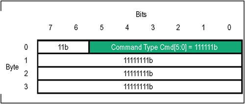 Table 4-3. HyperTransport Sync Packet Bit Assignments | Byte | Bit | Function | | | 5:0 | Sync Command Code . This is the six bit command code for a Sync information packet. Value = 111111b. | | | 7:6 | Reserved . Must be driven to 1's. | | 3:1 | 7:0 | Reserved . Must be driven to 1's. | Control Packets: Requests As shown previously in Table 4-1 on page 69, there are a number of different request types; each variant has a slightly different way of using the fields within its request packet. In this section, the basic packet format layout used by the principal request types is covered, including Sized Read (always non-posted), Sized Write (posted and non-posted), Broadcast Message (always posted), Flush (always non-posted), Fence (always posted), and Atomic Read-Modify-Write (always non-posted). Sized Read And Sized Write Requests The eight-byte sized read and sized write packets (abbreviated RdSized and WrSized in the Specification) are the mainstream commands used to perform most of the data transfers to both memory or I/O in HyperTransport. Some of the options available with sized read and write requests are: -
Byte or dword read/write data transfers; valid data transferred ranges from 0 bytes to 64 bytes (16 dwords). -
Posted or non-posted virtual channel for writes. Reads are always split transactions traveling in the non-posted virtual channel. -
Isochronous posted or non-posted virtual channels for the request and any subsequent response. Isochronous flow control buffers are required to support this traffic. -
Coherency option bit which indicates whether the transaction requires enforcement of host cache coherency. If the transaction does not target host memory, this feature does not apply. -
Assignment of a non-zero Sequence ID attribute to requests forces other devices to maintain strict ordering for all requests from same source. A Sequence ID of 0 indicates that there is no strict ordering required. -
Use of reserved ranges in RdSized and WrSized request packet address fields to support special-case transactions, including configuration cycles, interrupt requests, and End-Of-Interrupt (EOI) messages, etc. Generic RdSized And WrSized Request Packet Format Figure 4-8 on page 76 depicts the various fields of the eight-byte Sized Read or Sized Write packet. Table 4-4 on page 76 summarizes the usage of each bit field. Figure 4-8. Control Packets: Generic Sized Read/Sized Write Requests 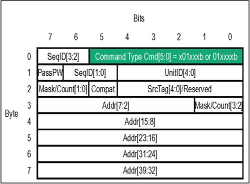 Table 4-4. HyperTransport Sized Read/Write Packet Bit Assignments | Byte | Bit | Function | | | 5:0 | Command Code . This is the six bit command code for RdSized and WrSized requests. x01xxxb = WrSized Request 001xxxb = RdSized Request Usage of bits marked "x": refer to Table 4-1 on page 69. | | | 7:6 | SeqID[3:2] . (also see Byte 1, bits 5,6). This field tags groups of requests that are part of a strongly ordered sequence. The SeqID value is assigned by the requestor ; all transactions within the same transaction stream and virtual channel, and having the same non-zero SeqID value must have their ordering maintained . The SeqID value of 0 is reserved, and indicates a transaction is not part of an ordered sequence. | | 1 | 4:0 | UnitID[4:0]. In a request, this field identifies the source of a transaction. UnitID of 0 is used by host bridges; non-zero UnitIDs are for interior devices. Because of this convention, requests with UnitID = 0 are moving downstream (from the bridge), and requests with UnitID > 0 are moving upstream (from an interior device). Physical devices are allowed to consume multiple UnitIDs. | | 1 | 6:5 | SeqID[1:0] . (also see Byte 0, bits 6,7). This is the other half of the 4-bit field used to tag groups of requests that are part of a strongly ordered sequence. The SeqID value of 0 is reserved, and indicates a transaction is not part of an ordered sequence. | | 1 | 7 | PassPW. When set, this bit indicates that this packet may pass packets in the posted request virtual channel of the same transaction stream. If the bit is clear, this packet must stay ordered behind them. | | 2 | 4:0 | SrcTag[4:0]. This 5-bit field is used as a transaction tag that uniquely identifies all outstanding transactions sourced by the same UnitID. Each UnitID may have up to 32 outstanding transactions at a time. The UnitID and SrcTag values together uniquely identify non-posted requests in a particular transaction stream. The SrcTag field is reserved and not used for posted requests. | | 2 | 5 | Compat. When set, this bit indicates that this request packet should only be claimed by the system subtractive decode device which is responsible for forwarding transactions to legacy devices (e.g. compatibility bridge). Requests with this bit set originate at the host bridge and travel downstream in the part of the topology called the "compatibility chain." | | 2 | 7:6 | Mask/Count[1:0]. (also see Byte 3 bits 0,1). This is the lower half of the 4-bit field that defines dword transfer count or valid bytes in a dword transfer. The meaning of this field depends on whether a byte/dword read or write transfer is being done: For (Sized) Byte Read transfers: This field is a 4 bit mask indicating which of the four bytes within the target dword are valid (much like byte enables in PCI). Any mask pattern is valid. For (Sized) Byte Write transfers : This (n-1) field indicates the total number of dwords to be transferred, plus the required dword write mask that precedes data. Example: If 6 dwords containing bytes of interest are to be transferred, the count field would be ((6 + 1)-1) = 6. For (Sized) Dword Read or Write transfers : This field is an n-1 count indicating the total number of dwords to be transferred. Again, a count of 0 = 1 dword; a count of 15d = 16 dwords. | | 3 | 1:0 | Mask/Count[3:2]. (also see Byte 2 bits 6,7). This is the upper half of the 4-bit field that defines which bytes are valid during a RdSized or WrSized transfer. The meaning of this field depends on whether a byte or dword transfer is being done. Refer to Byte 2, bits 7:6 above. | | 3 | 7:2 | Start Address[7:2] (also see Bytes 4-7 bits 0-7) This field provides the lowest bits of the dword-aligned, 40 bit HyperTransport target start address. Refer to the HyperTransport address map for a detailed description of the address ranges set aside for memory, I/O, configuration cycles, broadcast messages, interrupts, etc. | | 7:4 | 7:0 | StartAddress[39:8] (also see Byte 3 bits 2-7) This field provides the upper bits of the 40 bit HyperTransport target start address. | RdSized And WrSized Requests: Transaction Limits Using the various request packet option bits when constructing RdSized and WrSized transactions makes it possible to perform byte and dword read and write transfers in a number of variations. The following section describes some of the key limits associated with RdSized and WrSized requests. RdSized And WrSized (Dword) Transactions Sized dword read and write transactions can transfer any number of contiguous dwords within a 64 byte, address-aligned block. The request packet Mask/Count field provides the number of dwords to be transferred, beginning at the start address and indexing addresses sequentially upward until the limit defined by the Mask/Count field is reached. All bytes in the range are considered valid. Dword read and write start addresses must be dword aligned. If the start address is 64 byte aligned, the transfer may include the entire 64 byte (16 dword) region; if the start address is not 64 byte aligned, the transfer can only go to the end of the current 64-byte address-aligned block. Dword requests which would cross 64 byte address boundaries must be broken into multiple transactions. RdSized (Byte) Transactions Sized byte read transactions can transfer any combination of bytes within one address-aligned dword; requests which would cross an aligned dword address boundary must be broken into multiple transactions. The request packet Mask/Count field provides the "byte enable" mask pattern, indicating which bytes are valid. Mask[0] qualifies byte 0, Mask[1] qualifies byte 1, etc. Any mask pattern is legal; mask bits can be ignored by targets reading from "pre-fetchable" locations (all four bytes in the target dword are always returned). WrSized (Byte) Transactions Sized byte write transactions can transfer any combination of bytes within a 32-byte address-aligned region. The request packet Mask/Count field provides the total number of dwords to be transferred including the required single dword "write mask" pattern. The mask itself is sent just ahead of the data byte payload, and indicates which of the data bytes that follow are valid. Mask bit[0] qualifies byte 0, Mask bit [31] qualifies byte 31, etc. Byte write start address must be dword aligned. If the start address is 32 byte aligned, the write transfer may be as large as the entire 32 byte (8 dword) region; if the start address is not 32 byte aligned, the transfer can only go to the end of the current 32 byte address-aligned block. Basically, start address bits [4:2] identify the first the valid dword of data within the 32-byte region defined by start address bits [39:5]. Byte write requests which would cross 32 byte address boundaries must be broken into multiple transactions. A couple of subtle things about these transfers: -
The entire dword (32 bit) mask is always sent ahead of the data payload, regardless of start address and number of bytes being transferred. Mask bit fields are cleared for all invalid bytes in the 32-byte region ahead of the start address, for all invalid bytes within the transfer range itself, and for all unsent bytes remaining in the 32-byte region beyond the transfer limit implied by the Mask/Count field. -
While it isn't illegal to send invalid dwords at the front and back of a WrSized (Byte) transfer, it is more efficient to adjust the start address and Mask/Count field to trim off completely invalid dwords in front of the first and after the last dwords containing at least one valid byte in the 32 byte aligned region. RdSized And WrSized Requests: Other Notes Coherency The coherency bit in the Command field of RdSized and WrSized request packets (Byte 0, bit 0) indicates whether host cache coherency is a concern when HyperTransport RdSized and WrSized requests target host memory. Some buses, such as PCI, require coherency enforcement any time a transaction originating in the I/O subsystem targets main memory. This can represent a serious performance hit as processors spend much of their time snooping internal caches for accesses which they may not cache anyway. HyperTransport uses the coherency bit in the Command field of the request packet to inform the system whether coherency actions are required. If the coherency bit is set: -
All HyperTransport writes targeting host memory result in the CPU updating or invalidating the relevant cache line. -
All HyperTransport reads targeting main memory must result in the latest copy being returned to the requestor. If the CPU has a modified cache line, the system must assure that this is the one returned to the requestor. If a device has no particular requirement for coherency, it may chose to keep the coherency bit cleared. In this case, the request will complete without any coherency events. Special Case: Forcing A Coherency Event. A RdSized (byte) targeting host memory with all Mask/Count bits set = 0 (no valid bytes) and coherency bit set = 1 in the request packet Command field causes a host coherency action, using the address provided in the read. One dword of invalid data will be returned. WrSized Requests And The Posted Bit Sized write request packets may or may not set the posted bit (bit 5 of the CMD field). The implications of this bit are as follows : If set, the bit indicates the write request will travel in the posted request virtual channel and that there will not be a response from the target. Each device in the transaction path may de-allocate its buffers as soon as the posted request is transmitted. This also means that the SrcTag field is not used (reserved) because posted writes have no outstanding responses to track. This is in contrast to non- posted requests which require a unique SrcTag field for each request issued. It the posted bit is not set, the requestor expects a confirmation that the data written has reached the destination ” and is willing to suffer the performance penalty and wait for it. Eventually, a Target Done response will be routed back to the original requestor. In HyperTransport, certain address ranges require non-posted writes; this includes configuration and I/O cycles. Errors During RdSized Transactions In the event of a read error (SizedRd command), a response and all requested data is returned to the requestor, even though some or all of the data is not valid. Proceeding with a " dummy " read of invalid data is mainly for the benefit of devices in the transaction path that have already allocated flow control buffer space for the returning data. These devices use the return of each byte to simplify de-allocation of buffer space. PassPW and Response May Pass Posted Requests bits HyperTransport supports the strict producer-consumer ordering model found in PCI systems. There are occasions when strict producer/consumer ordering may not be required. In these cases, devices are allowed some flexibility in reordering of posted and non-posted request packets, as well as response packets. Ordering rules, including relaxed ordering, are described in more detail in the chapter entitled Ordering. Relaxing ordering rules is application-specific, and may provide better system performance in some cases. The source of a transaction indicates whether or non relaxed ordering is permitted through the setting or clearing of two bits in a request: -
PassPW bit . The PassPW request packet bit (Byte 1, bit 7) is programmed in the request packet and affects how ordering rules are applied to request as it moves toward the target. If set = 1, relaxed ordering is enabled; if PassPW is clear, relaxed ordering is not allowed. -
Response May Pass Posted Requests bit . For RdSized transactions, there is also a bit in the Command field of the RdSized request packet called Response May Pass Posted Requests (Byte 0, bit 3). This bit state will be replicated in the PassPW bit of the returning response and affects how ordering rules are applied to response as it moves back to the original source. The Response May Pass Posted Requests bit does not apply to commands other than RdSized. For reads, the bit should be cleared if the strict producer/consumer ordering model is required; otherwise this bit and the PassPW bit should both be set in the request. Compatibility Bit In keeping with PCI subtractive decoding, HyperTransport may use the Compat bit in RdSized and WrSized request packets (Byte 2, bit 5) to enable them to reach legacy hardware (e.g. boot firmware) behind the system subtractive decoder. When the Compat bit is set, all system devices should pass the request downstream through the "compatibility chain" to the subtractive decoder. Only the subtractive decoder may claim these transactions. The Compat bit is reserved and must not be set for upstream requests or configuration cycles. Broadcast Message Requests The eight-byte Broadcast Message request initiates a global message to all enabled HyperTransport devices. They are issued by host bridges, and travel only in the downstream direction. Implementation of Broadcast Message schemes are system-specific, so the use of address and many other fields is left to designers. Basic format is shown in Figure 4-9 on page 82. Table 4-5 on page 83 summarizes the usage of each defined bit field. Figure 4-9. Control Packets: Broadcast Message Request 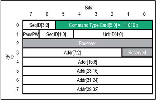 Table 4-5. HyperTransport Broadcast Message Packet Bit Assignments | Byte | Bit | Function | | | 5:0 | Broadcast Message Request Command Code . This is the six bit command code for a Broadcast Message request packet. Value = 111010b. | | | 7:6 | SeqID[3:2] . (also see Byte 1, bits 5,6). This field tags groups of requests that are part of a strongly ordered sequence. The SeqID value is assigned by the requestor; all transactions within the same transaction stream and virtual channel, and having the same non-zero SeqID value must have their ordering maintained. The SeqID value of 0 is reserved, and indicates a transaction is not part of an ordered sequence. | | 1 | 4:0 | UnitID[4:0] . Must be 0. In a request, this field identifies the source of a transaction. UnitID of 0 is used by host bridges; non-zero UnitIDs are for interior devices. Because of this convention, requests with UnitID = 0 (such as Broadcast Message) only move downstream. | | 1 | 6:5 | SeqID[1:0] . (also see Byte 0, bits 6,7). This is the other half of the 4-bit field used to tag groups of requests that are part of a strongly ordered sequence. The SeqID value of 0 is reserved, and indicates a transaction is not part of an ordered sequence. | | 1 | 7 | PassPW. Reserved because Broadcast Message always travels in posted virtual channel so a response is not required. | | 2 | 7:0 | These bits are reserved for a Broadcast Message because SrcTag isn't needed (posted request), Mask/Count isn't needed (no data packet), and the Compatibility bit is never set for these messages. | | 3 | 1:0 | SeqID[1:0] . (also see Byte 0, bits 6,7). This is the other half of the 4-bit field used to tag groups of requests that are part of a strongly ordered sequence. The SeqID value is assigned by the requestor; all transactions within the same transaction stream and virtual channel, and having the same non-zero SeqID value must have their ordering maintained. The SeqID value of 0 is reserved, and indicates a transaction is not part of an ordered sequence. | | 3 | 1:0 | Reserved . Mask/Count isn't needed for Broadcast Messages (no data packet) | | 3 | 7:2 | Start Address[7:2] (also see Bytes 4-7 bits 0-7) This field provides the lowest bits of the dword-aligned, 40 bit HyperTransport target start address. Broadcast Message usage of this field is system specific. | | 7:4 | 7:0 | Start Address[39:8] (also see Byte 3 bits 2-7) This field provides the upper bits of the 40 bit HyperTransport target start address. Broadcast Message usage of this field is system specific | Flush Requests One of the hazards of posted write buffers is that there is no certainty about when the data actually arrives at the destination because no response is ever expected (or sent). The four-byte Flush request guarantees that all previous posted writes within the same transaction stream are "globally visible" in host memory. Flush behaves like a dummy read operation in that it is a non-posted request followed by a response (Target Done) which simply indicates that the Flush operation is complete all of the way to the host bridge. The Flush request format is shown in Figure 4-10 on page 85. Table 4-6 immediately following summarizes the usage of each defined bit field. Figure 4-10. Control Packets: Flush Request 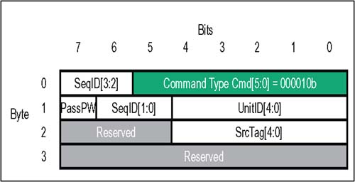 Table 4-6. HyperTransport Flush Packet Bit Assignments | Byte | Bit | Function | | | 5:0 | Flush Request Command Code . This is the six bit command code for a Flush request packet. Value = 000010b. | | | 7:6 | SeqID[3:2] . (also see Byte 1, bits 5,6). Must be 0. This is half of the 4-bit field used to tag groups of requests that are part of an ordered sequence within a particular transaction stream and virtual channel. The SeqID value must be 0 for Flush requests because they are never part of an ordered sequence. | | 1 | 4:0 | UnitID[4:0] . This field identifies the source of the Flush request. | | 1 | 6:5 | SeqID[1:0] . (also see Byte 0, bits 6,7). Must be 0. This is the other half of the 4-bit field used to tag groups of requests that are part of an ordered sequence within a particular transaction stream and virtual channel. The SeqID value must be 0 for Flush requests because they are never part of an ordered sequence. | | 1 | 7 | PassPW. Must be 0 in a Flush operation in order for the Flush to accomplish its task of pushing posted writes ahead of it. | | 2 | 4:0 | SrcTag[4:0]. This 5-bit field is used as a transaction tag that uniquely identifies all transactions in progress by the same UnitID. Each UnitID may have up to 32 outstanding transactions at a time. The UnitID and SrcTag values together uniquely identify non-posted requests in a particular transaction stream, including Flush. | | 2 | 7:5 | Reserved . Mask/Count and Compat bits are reserved in Flush request packets because no data is returned with the Target Done response and these requests never target the compatibility bus. | | 3 | 7:0 | Reserved. | Flush Requests: Transaction Limits The Flush request is a tool used to manage posted writes headed toward host memory. Two important limitations of the Flush request are: -
If the posted writes target memory other than host memory (e.g. peer-to-peer transfers), then the flush request and response only guarantee that the posted writes have reached the destination host bridge, not the ultimate target. After the host bridge re-issues all peer-to-peer requests downstream towards the intended targets, it sends the target done response back to the original requestor; it is entirely possible the flush response (target done) will reach the original requestor before the request is seen at the target. -
Flushes have no impact on the isochronous virtual channels. If isochronous flow control is not enabled on a link, then packets which do have the Isoc bit set actually travel in the normal virtual channels and will be affected by Flush requests. Fence Requests Another tool in the management of posted write transactions is the HyperTransport Fence command. The main features of the Fence request are: -
A Fence request provides a barrier between posted writes which applies to all UnitID's (transaction streams). This is different from the Flush which is specific to the posted writes associated with a single transaction stream. When the Fence is decoded by the bridge, it sends any previously posted writes in its buffers toward memory. As always, ordering is maintained for posted writes within individual single transaction streams, but no particular ordering is required for different streams. -
The Fence request travels in the posted virtual channel, meaning that there is no response expected or sent. The Fence request format is shown in Figure 4-11 on page 87. Table 4-7 immediately following summarizes the usage of each defined bit field. Figure 4-11. Control Packets: Fence Request 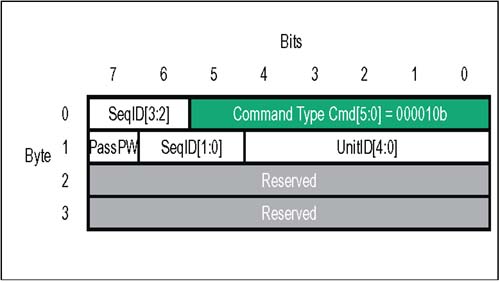 Table 4-7. HyperTransport Fence Packet Bit Assignments | Byte | Bit | Function | | | 5:0 | Fence Request Command Code . This is the six bit command code for a Fence request packet. Value = 000010b. | | | 7:6 | SeqID[3:2] . (also see Byte 1, bits 5,6). Must be 0. This is half of the 4-bit field used to tag groups of requests that are part of an ordered sequence within a particular transaction stream and virtual channel. The SeqID value must be 0 for Fence requests because they are never part of an ordered sequence. | | 1 | 4:0 | UnitID[4:0] . This field identifies the source of the Fence request. | | 1 | 6:5 | SeqID[1:0] . (also see Byte 0, bits 6,7). Must be 0. This is the other half of the 4-bit field used to tag groups of requests that are part of an ordered sequence within a particular transaction stream and virtual channel. The SeqID value must be 0 for Fence requests because they are never part of an ordered sequence. | | 1 | 7 | PassPW. Must be 0 in a Fence operation in order for the Fence to accomplish its task of pushing all previously posted writes ahead of it. | | 2 | 7:0 | Reserved . SrcTag, Mask/Count and Compat bits are reserved in Fence request packets because posted requests don't use SrcTags, no data is associated with the Fence request, and these requests never target the compatibility bus. | | 3 | 7:0 | Reserved. | Fence Requests: Transaction Limits The Fence request is a tool used to manage posted writes headed toward host memory from all transaction streams. Limitations of the Fence request include: -
Fence requests are issued from a device to a host bridge, or from one host bridge to another. While a tunnel forwards fence requests it sees, tunnels and single-link cave devices are never the target of a fence request and are never required to perform the fence function internally. -
Fences have no impact on the isochronous virtual channels. If isochronous flow control is not enabled, then other packets which do have the Isoc bit set actually travel in the normal virtual channels and will be affected by fence requests. -
If a fence request is seen by an end-of-chain device, it decodes the transaction and drops it. It may optionally choose to log the event as an end-of-chain error. Atomic Read-Modify-Write Requests While sized read and sized write requests can handle most general purpose HyperTransport data transfers, there are times when a combined, or atomic, read/write command is needed. Two Problems In Shared Memory Schemes Two problems related to shared memory schemes include: -
A memory location may be used for storing a "semaphore" to be checked by multiple devices (e.g. CPUs or I/O masters) before using a shared system resource. If the contents of the semaphore location indicate the resource is available, the device which reads it then over-writes the semaphore value to indicate the resource is now busy. If another agent reads the semaphore location and sees it is busy, it must wait until the agent using it clears the semaphore location, thus indicating it is again free. The problem arises when a sharing agent has read the semaphore and found the device is not busy. Before it over-writes the data value to claim the resource, another agent reads the semaphore location and also concludes the device is not busy. Now there is a race condition which can result in both devices attempting to over-write the semaphore and use the resource. -
The second problem is simpler. If a shared memory location is being used as an accumulator , agents will periodically read the current value, add a constant to it, and write the result back. Again, there is a hazard that the location will be read by one agent and before it can modify it and write it back, another agent may read it with a similar intention . In this case, one of the addends may be lost from the sum. Most modern bus protocols that support shared memory include a mechanism to avoid the conditions just described. HyperTransport uses the Atomic Read-Modify-Write request for this purpose. The purpose of the Atomic RMW is to force a one-qword (8 byte) memory location to remain "locked" for the duration of the read/modify/write operation required to check and change the targeted location. No other agent is allowed to access the address carried by the Atomic RMW request packet until the entire transaction completes. It is the responsibility of the bridge managing the memory to enforce the locking mechanism. As a transaction, the Atomic RMW behaves like non-posted write that generates a read response. The read response is accompanied by a single qword of data ” the value read from the targeted memory location before any changes are made. Atomic RMW Variants The Atomic Read-Modify-Write request has two variants that are designed to address the two cases just described. Compare And Swap The Compare and Swap variant of the Atomic RMW sends two qwords of data with the request. One qword (the compare value) is to be checked against the current value in memory; the other qword (the input value) is the data to be written to the memory location if the compare value is equal to the current value. If the compare value is not equal to the current value, the input value is not written to memory. In either case, a read response will be returned accompanied by the original qword read from memory. Fetch And Add The Fetch and Add variant of Atomic RMW sends a single qword (the input value) of data with the request. When the Atomic RMW reaches the bridge to main memory, the bridge unconditionally reads the current value from memory, adds the input value to it, and writes the result back to memory. The memory location remains locked to other transactions while the read-modify-write is in progress. A read response is then returned to the requestor, accompanied by the original qword read from memory. The Atomic RMW request format is shown in Figure 4-12 on page 91. Table 4-8 on page 91 summarizes the usage of each defined bit field. Figure 4-12. Control Packets: Atomic Read-Modify-Write Request 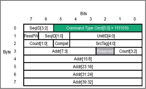 Table 4-8. HyperTransport Atomic Read ” Modify-Write Packet Bit Assignments | Byte | Bit | Function | | | 5:0 | Atomic RMW Request Command Code . This is the six bit command code for a Atomic Read-Modify-Write request packet. Value = 111101b. | | | 7:6 | SeqID[3:2] . (also see Byte 1, bits 5,6). This field tags groups of requests that are part of a strongly ordered sequence. The SeqID value is assigned by the requestor; all transactions within the same transaction stream and virtual channel, and having the same non-zero SeqID value must have their ordering maintained. The SeqID value of 0 is reserved, and indicates a transaction is not part of an ordered sequence. | | 1 | 4:0 | UnitID[4:0] . This field identifies the source of the Atomic RMW request. | | 1 | 6:5 | SeqID[1:0] . (also see Byte 0, bits 6,7). This is the other half of the 4-bit field that tags groups of requests that are part of a strongly ordered sequence. The SeqID value is assigned by the requestor; all transactions within the same transaction stream and virtual channel and having the same SeqID value must have their ordering maintained. | | 1 | 7 | PassPW. Must be 0 in an Atomic RMW operation. | | 2 | 4:0 | SrcTag[4:0]. This 5-bit field is used a transaction tag that uniquely identifies all transactions in progress by the same UnitID. Each UnitID may have up to 32 outstanding transactions at a time. The UnitID and SrcTag values together uniquely identify non-posted requests in a particular transaction stream, including Flush. | | 2 | 5 | Compat. Normally 0. When set, this bit indicates that this packet should only be claimed by the system subtractive decode device which is responsible for forwarding transactions to legacy devices (e.g. compatibility bridge). Atomic RMW transactions normally target host bridges, so this bit is clear. | | 2 | 7:6 | Mask/Count[1:0]. (also see Byte 3 bits 0,1). This is the lower half of the 4-bit field used to define which bytes are valid during a transfer. The value programmed in the count field depends on the variant of Atomic RMW request: For Fetch And Add RMW : Count field is set = 1 which indicates 2 dwords (1 qword of data sent with request). For Compare And Swap RMW : This field is set = 3 which indicates 4 dwords (2 qwords of data sent with request). | | 3 | 1:0 | Mask/Count[3:2]. (also see Byte 2 bits 6,7). This is the upper half of the 4-bit field that defines which bytes are valid during a transfer. The value programmed in the count field depends on the variant of Atomic RMW request: For Fetch And Add RMW : Count field is set = 1 which indicates 2 dwords (1 qword of data sent with request). For Compare And Swap RMW : This field is set = 3 which indicates 4 dwords (2 qwords of data sent with request). | | 3 | 7:3 | Start Address[7:3] (also see Bytes 4-7 bits 0-7) This field provides the lowest bits of the dword-aligned, 40 bit HyperTransport target start address. For an Atomic RMW, a qword aligned start address must be provided. | | 7:4 | 7:0 | Start Address[39:8] (also see Byte 3 bits 2-7) This field provides the upper bits of the 40 bit HyperTransport target start address. (See previous field). | Atomic RMW Requests: Transaction Limits The Atomic RMW request locks a qword memory address block while a read-modify-write operation is performed. Limitations of the Atomic RMW request include: -
The request transfer size, as indicated in the Mask/Count field, is restricted to either one or two qwords. Following the request, a read response returns a single qword of data from memory. -
These transactions are designed to be generated by I/O devices or bridges, and target system memory. Other than the host bridge, no HyperTransport devices are expected to support atomic operations. If a target detects an unsupported RMW, it may return a one qword read response with the error bit set or perform a non-atomic read-modify-write. The current HyperTransport Specification does not require peer-to-peer reflection of Atomic RMW. Control Packets: Responses There are two response types used in HyperTransport: Read Response and Target Done. Responses are returned by target devices following a non-posted request, and much of the response packet field information is extracted from the requests that caused them. Because responses are routed back to the original requestor either implicitly or based on UnitID, they don't require a 40 bit address field like requests do. All response packets are four bytes. Read Responses The four-byte read response is returned when data requests are made, including RdSized and Atomic RMW requests. All HyperTransport read transactions are non-posted and split; this means that data is never returned immediately as it generally is on buses such as PCI. The advantage of split reads is that the latency involved, in waiting for a target to access its internal memory before returning read data, can be minimized by sending the request, releasing the bus, and waiting for the target to initiate the return of data when it has it. In HyperTransport, the read response is used by the target to indicate the return of previously requested data. The read response immediately precedes the data, and contains the following general information: -
The response packet type. -
Whether the response should travel in the standard or isochronous virtual channel. -
UnitID which acts as an address for responses. -
A direction bit indicating whether the response is moving upstream or downstream. -
Whether relaxed ordering may be used for this response relative to posted writes moving in the same stream. -
Error bits indicating whether or not the returning data can be considered valid; if it is invalid, error bits indicate whether the error occurred at the target or if the request inadvertently reached an end-of-chain device. Figure 4-13 on page 95 depicts the various fields of the four-byte read response packet. Table 4-9 on page 95 summarizes the usage of each bit field. Figure 4-13. Control Packets: Read Response 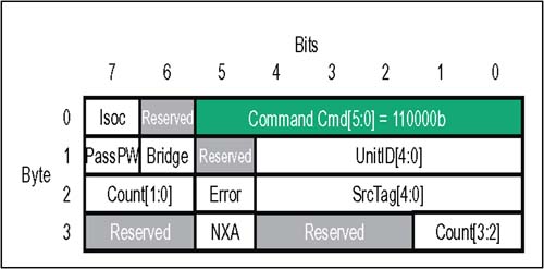 Table 4-9. HyperTransport Read Response Packet Bit Assignments | Byte | Bit | Function | | | 5:0 | Command Code . This is the six bit command code for the Read Response packet. Value: 110000b | | | 6 | Reserved. | | | 7 | Isoc . If set = 1, this response should travel in the isochronous virtual channels for responses and response data. This bit is set in the target response if the Isoc bit was set in the request (Command field) that caused it. Note: The state of this bit should be preserved even when passing through tunnel devices with isochronous flow control disabled. | | 1 | 4:0 | UnitID[4:0] . (also see Bridge bit below). This field helps route the responses and is programmed in two different ways: For Upstream Responses (Bridge = 0): This field contains the UnitID of the node that generated the response (original target) For Downstream Responses (Bridge = 1): This field contains the UnitID of the original requestor | | 1 | 6 | Bridge . This bit is set by host bridges to indicate responses which are traveling downstream. Interior devices use Bridge bit and UnitID to claim returning responses. Upstream responses from interior devices have the Bridge bit cleared and carry the UnitID of the responder , meaning that they are routed implicitly to host bridge based only on the fact that the Bridge bit = 0. | | 1 | 7 | PassPW. This bit will be set in the read response if response may pass posted requests bit was set in the command field of the read request that caused it. If set, relaxed ordering may be applied. | | 2 | 4:0 | SrcTag[4:0]. This field is copied from the request packet. | | 2 | 5 | Error. When set, this bit indicates that an error occurred during the read transaction. All of the requested data is returned, even if there is an error. | | 2 | 7:6 | Count[1:0]. (also see Byte 3 bits 0,1). This is the lower half of the 4-bit field that indicates the quantity of returning data: For Dword Read transfers: This field is a copy of the count field in the request packet For Byte Read transfers : Count field is always set = 0 (1 dword) For Atomic RMW transfers : Count field is always set = 1 (2 dwords =1 qword). | | 3 | 1:0 | Count[3:2]. (also see Byte 2 bits 6,7). This is the upper half of the 4-bit field that indicates the quantity of returning data: For Dword Read transfers: This field is a copy of the count field in the request packet For Byte read transfers : Count field is always set = 0 (1 dword) For Atomic RMW transfers : Count field is always set = 1 (2 dwords = 1 qword). | | 3 | 4:2 | (Reserved. | | 3 | 5 | NXA (Non-Existent Address) This bit is only valid if Error bit (Byte 2, bit 5) is set. If NXA and Error are both set = 1, error occurred at end-of-chain device due to a non-existent address problem. If NXA = 0 and Error is set = 1, then error occurred at target. | | 3 | 7:6 | Reserved. | Target Done Responses The four-byte target done response is returned when non-posted WrSized or Flush requests are made. As no data is returned with the target done response, it is routed back to the original requestor as a way to confirm the completion of a write transaction or a Flush operation. The contents of the target done response packet are very similar to the read response packet except that no mask/count information is required because there is no data to transfer. Figure 4-14 on page 97 depicts the various fields of the four-byte read response packet. Table 4-10 summarizes the usage of each bit field. Figure 4-14. Control Packets: Target Done Response 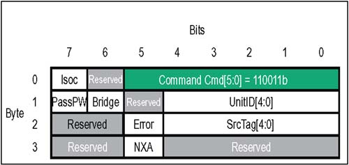 Table 4-10. HyperTransport Target Done Response Packet Bit Assignments | Byte | Bit | Function | | | 5:0 | Command Code . This is the six bit command code for the Target Done Response packet. Value: 110011b | | | 6 | Reserved. | | | 7 | Isoc . If set = 1, this response should travel in the isochronous virtual channels for responses and response data. This bit is set in the target done response if the Isoc bit was set in the request (Command field) that caused it. Note: The state of this bit should be preserved even when passing through tunnel devices with isochronous flow control disabled. | | 1 | 4:0 | UnitID[4:0] . (also see Bridge bit below). This field helps route the responses, and is programmed in two different ways: For Upstream Responses (Bridge = 0): This field contains the UnitID of the node which generated the response (original target) For Downstream Responses (Bridge = 1): This field contains the UnitID of the original requestor | | 1 | 6 | Bridge . This bit is set by host bridges to indicate responses which are traveling downstream. Interior devices use Bridge bit and UnitID to claim returning responses. Upstream responses from interior devices have the Bridge bit cleared and carry the UnitID of the responder, meaning that they are routed implicitly to host bridge based only on the fact that the Bridge bit = 0. | | 1 | 7 | PassPW. This bit is set in the target done response if relaxed ordering of the target done response is permitted. As there is no response may pass posted requests bit in write requests, it is device-specific whether this response packet bit is set or not. Generally, it is expected to be set. | | 2 | 4:0 | SrcTag[4:0]. This field is copied from the request that caused this target done response. | | 2 | 5 | Error. When set, this bit indicates that an error occurred during the transaction. | | 2 | 7:6 | Reserved | | 3 | 4:0 | Reserved | | 3 | 5 | NXA (Non-Existent Address) This bit is only valid if Error bit (Byte 2, bit 5) is set. If NXA and Error are both set = 1, error occurred at end-of-chain device due to a non-existent address problem. If NXA = 0 and Error is set = 1, then error occurred at target. | | 3 | 7:6 | Reserved. |  |