Background: IO Subsystem Bottlenecks
Background: I/O Subsystem BottlenecksNew I/O buses are typically developed in response to changing system requirements and to promote lower cost implementations . Current-generation I/O buses such as PCI are rapidly falling behind the capabilities of other system components such as processors and memory. Some of the reasons why the I/O bottlenecks are becoming more apparent are described below. Server Or Desktop Computer: Three SubsystemsA server or desktop computer system is comprised of three major subsystems:
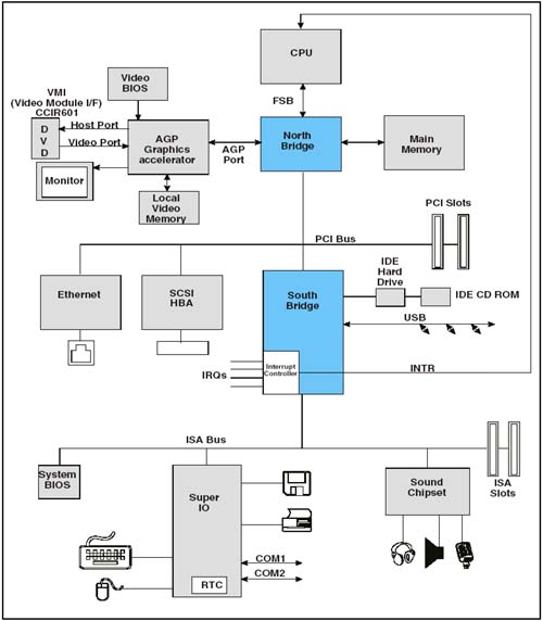
CPU Speed Makes Other Subsystems Appear SlowBecause of improvements in CPU internal execution speed, processors are more demanding than ever when they access external resources such as memory and I/O. Each external read or write by the processor represents a huge performance hit compared to internal execution. Multiple CPUs Aggravate The ProblemIn systems with multiple CPUs, such as servers, the problem of accessing external devices becomes worse because of competition for access to system DRAM and the single set of I/O resources. DRAM Memory Keeps Up Fairly WellAlthough it is external to the processor(s), system DRAM memory keeps up fairly well with the increasing demands of CPUs for a couple of reasons. First, the performance penalty for accessing external memory is mitigated by the use of internal processor caches. Modern processors generally implement multiple levels of internal caches that run at the full CPU clock rate and are tuned for high "hit rates". Each fetch from an internal cache eliminates the need for an external bus cycle to memory. In addition, in cases where an external memory fetch is required, DRAM technology and the use of synchronous bus interfaces to it (e.g. DDR, RAMBUS, etc.) have allowed it to maintain bandwidths comparable with the processor external bus rates. I/O Bandwidth Has Not Kept PaceWhile the processor internal speed has raced forward, and memory access speed has managed to follow along reasonably well with the help of caches, I/O subsystem evolution has not kept up. This Slows Down The ProcessorAlthough external DRAM accesses by processors can be minimized through the use of internal caches, there is no way to avoid external bus operations when accessing I/O devices. The processor must perform small, inefficient external transactions which then must find their way through the I/O subsystem to the bus hosting the device. It Also Hurts Fast PeripheralsSimilarly, bus master I/O devices using PCI or other subsystem buses to reach main memory are also hindered by the lack of bandwidth. Some modern peripheral devices (e.g. SCSI and IDE hard drives ) are capable of running much faster than the busses they live on. This represents another system bottleneck. This is a particular problem in cases where applications are running that emphasize time-critical movement of data through the I/O subsystem over CPU processing. Reducing I/O BottlenecksTwo important schemes have been used to connect I/O devices to main memory. The first is the shared bus approach, as used in PCI and PCI-X. The second involves point-to-point component interconnects, and includes some proprietary busses as well as open architectures such as HyperTransport. These are described here, along with the advantages and disadvantages of each. The Shared Bus ApproachFigure 1-1 on page 12 depicts the common "North-South" bridge PCI implementation. Note that the PCI bus acts as both an "add-in" bus for user peripheral cards and as an interconnect bus to memory for all devices residing on or below it. Even traffic to and from the USB and IDE controllers integrated in the South Bridge must cross the PCI bus to reach main memory. Figure 1-1. Typical PCI North-South Bridge System Until recently, the topology shown in Figure 1-1 on page 12 has been very popular in desktop systems for a number of reasons, including:
Unfortunately, some of the things that made this topology so popular also have made it difficult to fix the I/O bandwidth problems which have become more obvious as processors and memory have become faster. A Shared Bus Runs At Limited Clock SpeedsThe fact that multiple devices (including PCB connectors) attach to a shared bus means that trace lengths and electrical complexity will limit the maximum usable clock speed. For example, a generic PCI bus has a maximum clock speed of 33MHz; the PCI Specification permits increasing the clock speed to 66MHz, but the number of devices/connectors on the bus is very limited. A Shared Bus May Be Host To Many Device TypesThe requirements of devices on a shared bus may vary widely in terms of bandwidth needed, tolerance for bus access latency, typical data transfer size, etc. All of this complicates arbitration on the bus when multiple masters wish to initiate transactions. Backward Compatibility Prevents Upgrading PerformanceIf a critical shared bus is based on an open architecture, especially one that defines user "add-in" connectors, then another problem in upgrading bus bandwidth is the need to maintain backward compatibility with all of the devices and cards already in existence. If the bus protocol is enhanced and a user installs an "older generation card", then the bus must either revert back to the earlier protocol or lose its compatibility. Special Problems If The Shared Bus Is PCIAs popular as it has been, PCI presents additional problems that contribute to performance limits:
A Note About PCI-XOther than scalability and the number of devices possible on each bus, the PCI-X protocol has resolved many of the problems just described with PCI. For third-party manufacturers of high performance add-in cards and embedded devices, the shared bus PCI-X is a straightforward extension of PCI which yields huge bandwidth improvements (up to about 2GB/s with PCI-X 2.0). ThePoint-to-Point Interconnect ApproachAn alternative to the shared I/O bus approach of PCI or PCI-X is having point-to-point links connecting devices. This method is being used in a number of new bus implementations, including HyperTransport technology. A common feature of point-to-point connections is much higher bandwidth capability; to achieve this, point-to-point protocols adopt some or all of the following characteristics:
A Note About ConnectorsWhile connectors may or may not be defined in a point-to-point link specification, they may be designed into some implementations to connect from board-board or for the attachment of diagnostic equipment. There is no definition of a peripheral add-in card connector for HyperTransport as there is in PCI or PCI-X. |
EAN: 2147483647
Pages: 182
- An Emerging Strategy for E-Business IT Governance
- Assessing Business-IT Alignment Maturity
- Measuring and Managing E-Business Initiatives Through the Balanced Scorecard
- A View on Knowledge Management: Utilizing a Balanced Scorecard Methodology for Analyzing Knowledge Metrics
- Measuring ROI in E-Commerce Applications: Analysis to Action