Numeric Error Handling (FERR and IGNNE)
Numeric Error Handling (FERR# and IGNNE#)The x86 processors that have integrated floating-point units provide support for DOS compatible error-handling. These processors have a numeric exception (NE) control bit in Control Register 0 that allows the programmer to select the error-handling scenario to be used by the processor when a floating-point error is detected . The error handling options are:
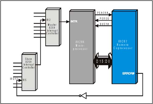
Prior to discussing the DOS-compatible method of error handling by the i486 and later processors, a brief description of floating-point operation and error handling is provided as background. Numeric Error Handling (The Original Method)The x86 floating-point solution prior to the i486 microprocessor included a separate numeric co-processor as illustrated in Figure 22-19 on page 517. Note that interface pins between the microprocessor and the numeric co-processor permit some communication, while other communication is initiated by the processor via I/O writes . For example, instructions are fetched only by the microprocessor, so when a floating-point instruction is detected, the processor forwards the instruction to the co-processor via a series of I/O write operations. During the execution of a floating-point instruction, the co-processor asserts the BUSY# signal to notify the processor that it has not yet completed the execution of the instruction. If an error occurs while executing the instruction, BUSY# remains asserted and the floating-point error is reported via the numeric co-processor error# signal. When the floating-point error is signaled, the following primary actions are taken:
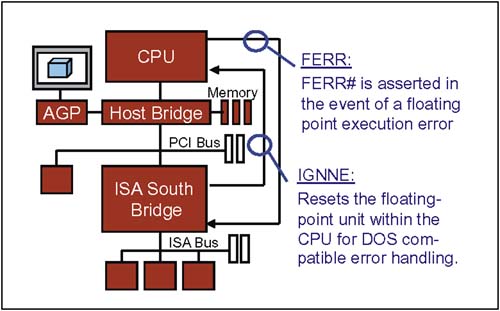
Figure 22-19. Legacy Numeric Coprocessor Error Reporting The error handler then executes an Interrupt Return instruction (IRET) allowing the processor to continue executing code from the point of the error. DOS-Compatible Error HandlingX86 processors that have an integrated floating-point unit implement a feature that allows PC-DOS-compatible floating-point error reporting and handling. The NE (Numeric Error) bit in Control Register 0 (CR0) must be cleared (0) to enable DOS-compatible error handling. When compatible error-handling is selected, two signals come into play as illustrated in Figure 22-20 on page 518:
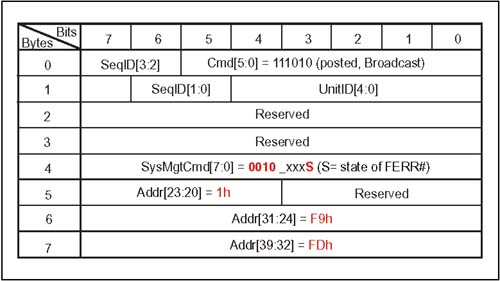
Figure 22-20. DOS Compatible Floating-Point Error Signaling When a floating-point error occurs, the processor asserts FERR# and freezes so that no further floating-point instructions are executed. This behavior is similar to that of the numeric co-processor in the previous legacy example. Note that steps 1-6 outlined in the legacy example are the same as those performed in this example. However, writing a data value of 00h to I/O location 0Fh as described in step 6 has a different effect using this solution. In the legacy solution, the I/O write targets the co-processor, but in this case the I/O write has no effect on the integrated FPU. Instead, external logic recognizes the I/O write and asserts IGNNE# in response. Recall that the processor freezes when an error is detected, but upon seeing IGNNE# asserted, the FPU restarts and continues to execute floating-point instructions. HT Method of Signaling FERR# and IGNNE#Figure 22-21 on page 519 illustrates an example HT system's implementation of FERR# and IGNNE#. The processor FERR# and IGNNE# signals connect directly to the Host Bridge. Figure 22-21. Example X86 System with Required DOS-Compatible FPU Error Handling HT Method of FERR# SignalingThe CPU asserts the FERR# signal that is monitored by the Host Bridge. The bridge responds by initiating a broadcast transaction to all downstream HT devices. Figure 22-22 illustrates the FERR message delivered by the Host Bridge. Figure 22-22. Format and Content of the SM FERR Message HT Method of IGNNE# SignalingDOS-compatible floating point error handlers perform writes to I/O location F0h to clear the floating point error (based on the legacy numeric coprocessor design). The ICH/South bridge includes an I/O decoder that detects the attempt to clear the FPU error and responds by issuing a IGNNE message to the Host bridge. The bridge then asserts the IGNNE# signal to notify the internal FPU that it can resume execution of floating point instructions. |

EAN: 2147483647
Pages: 182