Shift Registers
|
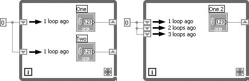
Shift registers, available for While Loops and For Loops, are a special type of variable used to transfer values from one iteration of a loop to the next (see Figure 6.14). They are unique to and necessary for LabVIEW's graphical structure; we'll talk more about their uses in a little while. You create a shift register by popping up on the left or right loop border and selecting Add Shift Register from the pop-up menu. Figure 6.14. Shift registers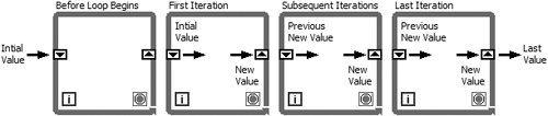 You can configure the shift register to remember values from several previous iterations, as shown in Figure 6.15, a useful feature when you are averaging data values acquired in different iterations. To access values from previous iterations, create additional terminals by popping up on the left terminal and choosing Add Element from the pop-up menu. Alternatively, you can create additional terminal elements by hovering over the Shift Register and dragging the grab handles that appear. Figure 6.15. A While Loop having one shift register with multiple left terminal elements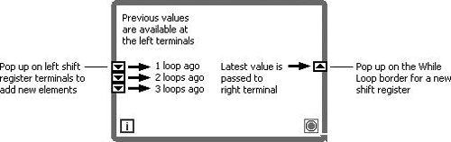 You can have many different shift registers storing many different variables on the same loop. Just pop up on the loop border and add them until you have as many pairs as you need. The left terminal will always stay parallel with its right terminal; if you move one, they both move. So if you have a lot of shift registers on your loop and can't tell exactly which ones are parallel, just select one and its partner will be automatically selected, or move one terminal a little and watch its mate follow. Don't make the common mistake of confusing multiple variables stored in multiple shift registers with a single variable stored from multiple previous iterations in one shift register. Figure 6.16 shows the difference. Figure 6.16. (Left) Two separate variables. (Right) Several loop values of one variable. If you're still a little confused, don't worry. Shift registers are a completely new and different concept, unlike anything you may have encountered in a traditional programming language. Stepping through the next exercise should demonstrate them more clearly for you.
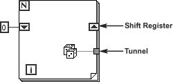
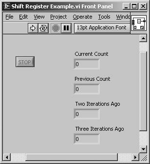
Make sure to wire directly to the shift register terminal so that you don't accidentally create an unrelated tunnel into or out of the loop. Figure 6.17 shows the difference between a shift register and a tunnel. Figure 6.17. Shift register and tunnel, two different ways of passing data through the walls of a loop Activity 6-2: Shift Register ExampleTo give you an idea of how shift registers work, you will observe their use to access values from previous iterations of a loop. In this VI, you will be retrieving count values from previous loops.
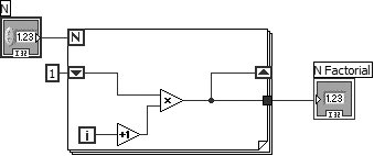
Why You Need Shift RegistersObserve the example illustrated in Figure 6.20. In loop (A), you are creating a running sum of the iteration count. Each time through the loop, the new sum is saved in the shift register. At the end of the loop, the total sum of 45 is passed out to the numeric indicator. In loop (B), you have no shift registers, so you cannot save values between iterations. Instead, you add zero to the current "i" each time, and only the last value of 9 will be passed out of the loop. Figure 6.20. Two loops showing the difference between shift registers (A) and tunnels (B) Or what about a case where you need to average values from successive loop iterations? Maybe you want to take a temperature reading once per second, and then average those values over an hour. Given LabVIEW's graphical nature, how could you wire a value produced in one loop iteration into the next iteration without using a shift register? Initializing Shift Registers
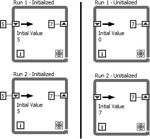
To avoid unforeseen and possibly nasty behavior, you should always initialize your shift registers unless you have a specific reason not to and make a conscious decision to that effect. To initialize the shift register with a specific value, wire that value to all the left terminals of the shift register from outside the loop, as shown in the left two loops in Figure 6.21. If you do not initialize it, the initial value will be the default value for the shift register data type the first time you run your program. In subsequent runs, the shift register will contain whatever values are left over from previous runs. Figure 6.21. Two loops (left and right) on subsequent iterations (top and bottom) showing the effect of uninitialized shift registers (right) vs. initialized shift registers (left) For example, if the shift register data type is Boolean, the initial value will be FALSE for the first run. Similarly, if the shift register data type is numeric, the initial value will be zero. The second time you run your VI, an uninitialized shift register will contain values left over from the first run! Study Figure 6.21 to make sure you understand what initialization does. The two loops in the left column show what happens when you run a program that contains an initialized shift register twice. The right column shows what happens if you run a program containing an uninitialized shift register two times. Note the initial values of the shift registers in the two bottom loops.
LabVIEW does not discard values stored in the shift register until you close the VI and remove it from memory. In other words, if you run a VI containing uninitialized shift registers, the initial values for the subsequent run will be the ones left over from the previous run. You seldom want this behavior (although there are some advanced uses such as the "Functional Global," which will be discussed in Appendix D, "LabVIEW Object-Oriented Programming") and the resulting problems can be very difficult to spot!
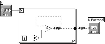
If you resize a shift register to show multiple previous iterations (on the left shift register), LabVIEW requires you to initialize all the shift register elements if any shift register elements are initialized. Otherwise, your VI will be broken (unable to run). The Feedback NodeGenerally, LabVIEW does not allow you to create a "cycle," where the output of block of code is used as the input for the same block of codeand attempting to do so will cause wires to become broken. You can see an example of a "cycle" in Figure 6.22. The cycle is broken due to the data flow rules, which state that (1) a node cannot execute until data flows into all of its input terminals and that (2) data does not flow out of a node's output terminals until the node finishes executing. Because a "cycle" uses the output terminals as a source for the input terminals, data can never flow into the input terminals because data will never flow out of the output terminals, because the node will not run until data flows into the input terminalsquite a paradox. Figure 6.22. A cycle, which is broken due to an input depending on an output However, if we are inside a While Loop or For Loop, we can place a Feedback Node in between the output terminal and the input terminal, and our code will now work. You can see an example of this in Figure 6.23. In fact, by default, LabVIEW will automatically place a Feedback Node in your cycle, when it is created, if you are inside a While Loop or For Loop. This setting is controlled by the Auto-insert Feedback Nodes in cycles checkbox in the Block Diagram section of the LabVIEW options dialog. Figure 6.23. A feedback node allows the cycle to work
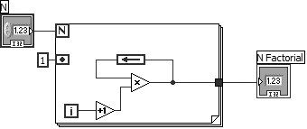
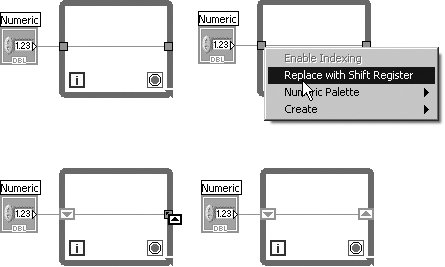
To understand exactly how the Feedback Node works, we should realize that a Feedback Node is really just a Shift Register in disguise. In fact, the code in Figure 6.23 is equivalent to the code in Figure 6.24. The first thing to note is that the arrow on the Feedback Node indicates the direction of data flow. The input terminal of the Feedback Node is equivalent to the right terminal of a Shift Register, and the output terminal of the Feedback node is equivalent to the left terminal of a Shift Register. For initializing a Feedback Node, we use the Initializer Terminal, which can be shown or hidden by right-clicking on the Feedback Node and selecting or deselecting the Initializer Terminal option. You can easily convert a Feedback Node to a Shift Register, and vice versa; simply right-click on the Feedback Node and select Replace with Shift Register or right-click on the Shift Register and select Replace with Feedback Node. Figure 6.24. A shift register created from a cycle (using the Replace with Shift Register feature) Converting Tunnels to Shift Registers (and Vice Versa)You may realize, in the process of writing your code, that a tunnel should in fact be replaced by a shift register. Fortunately, LabVIEW makes this very easysimply right-click on the tunnel and select Replace with Shift Register from the pop-up menu (Figure 6.25). Figure 6.25. Replacing input and output tunnels with a shift register
Shift Register Cursor The first thing you will notice is that the tunnel is replaced by a shift register. Also, you will notice that the mouse cursor now appears as a Shift Register Cursor. Use this cursor to select (mouse-click) another tunnel that you wish to convert to the opposing side of the shift register, or click anywhere on or inside the loop to place the opposing side of the shift register without converting another tunnel (see Figure 6.25). To convert a shift register into tunnels, simply right-click on the shift register and select Replace with Tunnels from the pop-up menu. |


EAN: 2147483647
Pages: 294