Block Diagrams
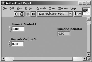
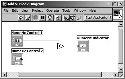
| The block diagram window holds the graphical source code of LabVIEW VIs. LabVIEW's block diagram corresponds to the lines of text found in a more conventional language like C or BASICit is the actual executable code. You construct the block diagram by wiring together objects that perform specific functions. In this section, we will discuss the various components of a block diagram: terminals, nodes, and wires. The simple VI shown in Figure 3.2 computes the sum of two numbers. Its diagram in Figure 3.3 shows examples of terminals, nodes, and wires. Figure 3.2. The front panel of Add.vi contains controls for data input and indicators for data display Figure 3.3. The block diagram of Add.vi contains terminals, nodes, and wires (the functional source code) When you place a control or indicator on the front panel, LabVIEW automatically creates a corresponding terminal on the block diagram. By default, you cannot delete a block diagram terminal that belongs to a control or indicator, although you may try to your heart's content. The terminal disappears only when you delete its corresponding control or indicator on the front panel.
You can allow the deletion of panel terminals on the block diagram by enabling the Delete/copy panel terminals from diagram option in the Block Diagram category of the Tools>>Options dialog (we will learn more about the LabVIEW Options dialog in Chapter 15). However, this is only recommended if you are very comfortable and experienced with editing LabVIEW VIs. It is very easy to mistakenly delete front panel controls and indicators without realizing it, because you may not be paying much attention to the front panel while editing the block diagram.
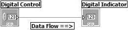
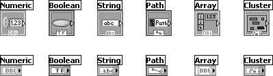
Control terminals have thick borders along with an arrow pointing out from the right, while indicator borders are thin and have an arrow pointing in from the left. It is very important to distinguish between the two because they are not functionally equivalent (Control=Input=data source and Indicator = Output = data sink, so they are not interchangeable). You can think of terminals as entry and exit ports in the block diagram, or as sources and destinations. Data that you enter into Numeric Control 1 (shown in Figure 3.4) exits the front panel and enters the block diagram through the Numeric Control 1 terminal on the diagram. The data from Numeric Control 1 follows the wire and enters the Add function input terminal. Similarly, data from Numeric Control 2 flows into the other input terminal of the Add function. Once data is available on both input terminals of the Add function, it performs its internal calculations, producing a new data value at its output terminal. The output data flows to the Numeric Indicator terminal and reenters the front panel, where it is displayed for the user. Figure 3.4. Block diagram with a control (input/source) terminal, an indicator (output/sink) terminal, and a wire through which data will flow View Terminals as IconsBlock diagram terminals have a View As Icon option (available from their pop-up menus), which causes them to be viewed as Icons. A terminal viewed as an icon is larger (than with the setting turned off) and contains an icon that reflects the terminal's front panel control type. With the View As Icon option turned off, a terminal will be more compact and display the data type more predominantly. The functionality is exactly the same for either setting; it's just a matter of preference. Figure 3.5 shows the terminals of several different front panel controls with the View As Icon option selected (top row) and with the option not selected (bottom row). Figure 3.5. Terminals with View As Icon setting enabled (top row) and disabled (bottom row) This setting is configurable for each terminal on the block diagram. You can choose whether terminals will be placed onto the block diagram as icons, by checking the Place front panel terminals as icons setting in the Block Diagram category of the Tools>>Options dialog. This LabVIEW option is turned on, by default. NodesA node is just a fancy word for a program execution element. Nodes are analogous to statements, operators, functions, and subroutines in standard programming languages. The Add and Subtract functions represent one type of node. A structure is another type of node. Structures can execute code repeatedly or conditionally, similar to loops and case statements in traditional programming languages. LabVIEW also has special nodes, called Formula Nodes, which are useful for evaluating mathematical formulas or expressions. In addition, LabVIEW has very special nodes called Event Structures that can capture front panel and user-defined events. WiresA LabVIEW VI is held together by wires connecting nodes and terminals. Wires are the data paths between source and destination terminals; they deliver data from one source terminal to one or more destination terminals.
If you connect more than one source or no source at all to a wire, LabVIEW disagrees with what you're doing, and the wire will appear brokena wire can only have one data source, but it can have multiple data sinks.
This principle of wires connecting source and destination terminals explains why controls and indicators are not interchangeable. Controls are source terminals, while indicators are destinations, or "sinks." Each wire has a different style or color, depending on the data type that flows through the wire. The block diagram shown in Figure 3.3 depicts the wire style for a numeric scalar valuea thin, solid line. The chart in Figure 3.6 shows a few wires and corresponding types. Figure 3.6. Basic wire styles used in block diagrams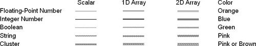 To avoid confusing your data types, simply match up the colors and styles! Dataflow ProgrammingGoing with the Flow
Because LabVIEW is not a text-based language, its code cannot execute "line by line." The principle that governs G program execution is called dataflow. Stated simply, a node executes only when data arrives at all its input terminals; the node supplies data to all of its output terminals when it finishes executing; and the data passes immediately from source to destination terminals. Dataflow contrasts strikingly with the control flow method of executing a text-based program, in which instructions are executed in the sequence in which they are written. This difference may take some getting used to. Although traditional execution flow is instruction driven, dataflow execution is data driven or data dependent. |


EAN: 2147483647
Pages: 294