Foundations of Networking
Upper Layers (Layers 5, 6, 7 Handle Application Issues)The upper layers of the OSI reference model are concerned with application issues. They are generally implemented only in software. The Application layer is the highest layer and is closest to the end user. Both users and Application layer processes interact with software applications containing a communications component.
Layer 7 Application Essentially, the Application layer acts as the end-user interface. This is the layer where interaction between the mail application (cc:Mail, MS Outlook, and so forth) or communications package and the user occurs. For example, when a user desires to send an e-mail message or access a file on the server, this is where the process starts. Another example of the processes going on at this layer are things like Network File System (NFS) use and the mapping of drives through Windows NT. Layer 6 Presentation The Presentation layer is responsible for the agreement of the communication format (syntax) between applications. For example, the Presentation layer enables Microsoft Exchange to correctly interpret a message from Lotus Notes. Another example of the actions occurring in this layer is the encryption and decryption of data in PGP (Pretty Good Privacy). Layer 5 Session The Session layer is responsible for the Application Layer s management of information transfer, to the Data Transport portion of the OSI reference model. An example is Sun s or Novell s Remote Procedure Call (RPC), this functionality uses Layer 5. Lower Layers (Layers 1, 2, 3, 4 Handle Data Transport Issues)The lower layers of the OSI reference model handle data transport issues. The Physical and Data Link layers are implemented in hardware and software. The other lower layers are generally implemented only in software. Layer 4 Transport The Transport layer is responsible for the logical transport mechanism, which includes functions conforming to the mechanism s characteristics. For example, the Transmission Control Protocol (TCP), a logical transport mechanism, provides a level of error checking and reliability to the transmission of user data to the lower layers of the OSI reference model. This layer is the only layer that provides true source-to-destination end-to-end connectivity. This layer also supports multiple connections based upon port as found in TCP or UDP. Layer 3 Network The Network layer determines physical interface address locations. Routing decisions are made based upon the locations of the Internet Protocol (IP) address in question. For example, IP addresses establish logical topologies known as subnets. Applying this definition to a LAN workstation environment, the workstation determines the location of a particular IP address and where its associated subnet resides through the Network layer. Therefore, a packet sent to IP address A.B.C.D will be forwarded through the workstation s Ethernet card and out onto the network.
Layer 2 Data Link The Data Link layer provides framing, error, and flow control across the network media being used. An important characteristic of this layer is that the information that is applied to it is used by devices to determine if the packet needs to be acted upon by this layer (that is, proceed to Layer 3 or discard). The Data Link layer also assigns a Media Access Control (MAC) address to every LAN interface on a device. For example, on an Ethernet LAN segment, all packets are broadcast and received by every device on the segment. Only the device whose MAC address is contained within this layer s frame acts upon the packet; all others do not. It is important to note at this point that serial interfaces do not normally require MAC addresses unless it is necessary to identify the receiving end.
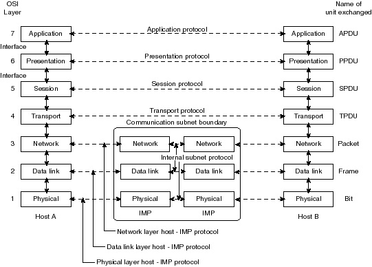
Layer 1 Physical The Physical layer is the lowest layer and is closest to the physical network medium (the network cabling connecting various pieces of network equipment, for example). It is responsible for actually placing information on the physical media in the correct electrical format (that is, raw bits). For example, an RJ45 cable is wired very differently from an Attachment Unit Interface (AUI); this means that the Physical layer must place the information slightly differently for each media type. Figure 1-5 shows the actual relationship (peering) between the seven layers.
|
EAN: 2147483647
Pages: 200