The Fundamentals of OSPF Routing Design
The following is an illustration of how the router will interpret these addresses. Please remember that any time you are using a mask different than the natural mask, the router will complain if the combination IP address and mask result in a subnet zero. To resolve this issue, use the ip subnet-zero command on the router: RTA# ip subnet-zero interface Ethernet2 ip address 192.214.11.10 255.255.255.128 interface Ethernet3 ip address 192.214.11.160 255.255.255.192 interface Ethernet4 ip address 192.214.11.226 255.255.255.192 RTA# show ip route connected 192.214.11.0 is variably subnetted, 3 subnets, 2 masks C 192.214.11.0 255.255.255.128 is directly connected, Ethernet2 C 192.214.11.128 255.255.255.192 is directly connected, Ethernet3 C 192.214.11.192 255.255.255.192 is directly connected, Ethernet4 Chapter SummaryThis chapter completes the discussion on the mathematics surrounding the SPF algorithm and its operation within OSPF. The various “golden rules of design” were provided for all of the essential portions of an OSPF network. Included within those discussions was the ability of OSPF to summarize routes and the benefits of using such a strong feature of the protocol. The discussion concluded with a demonstration of VLSM’s usefulness within the OSPF environment. In conclusion, many of the OSPF-specific configuration commands will be presented in detail in the next chapter. All of the configuration commands are grouped together for your ease of reference In addition, a complete list and definition of the commands will be provided in Chapter 7, “Designing & Implementing an OSPF Network.” OSPF Case Study: Point-to-Multipoint Link NetworksThe objective of this case study is to demonstrate how to design, configure, and troubleshoot an OSPF point-to-multipoint link network. This feature’s importance is linked with the increased use of Frame Relay due to reduced cost for the service. As customers used point-to-multipoint on nonbroadcast media (Frame Relay), they found that their routers could not dynamically discover their neighbors. The OSPF point-to-multipoint link feature allows the neighbor command to be used on point-to-multipoint interfaces. The use of point-to-multipoint can be used to minimize the number of IP addresses that are used and basically enable the user to configure a nonbroadcast media similarly to a LAN. Before the OSPF point-to-multipoint link feature, some OSPF point-to-multipoint protocol traffic was treated as multicast traffic. This meant that the neighbor command was not needed for point-to-multipoint interfaces because multicast took care of the traffic. In particular, multicast hellos discovered all neighbors dynamically. Also, on any point-to-multipoint interface (broadcast or not), the Cisco IOS software assumed that the cost to each neighbor was equal. In reality, the bandwidth to each neighbor can be different; therefore, the cost should be different because the OSPF point-to-multipoint link enables you to configure a separate cost for each neighbor.
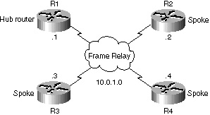
Another advantage is that you do not need to use subinterfaces with this feature. Subinterfaces count toward the practical upper limit of 300 IDBs (Interface Descriptor Blocks). There is an IDB assigned for each physical and software interface that is configured on the router. This includes any subinterfaces. There is no command that will tell you how many IDBs have been used. In other words, Cisco IOS currently supports less then 300 interfaces on the router (real or virtual) unless you have an 11.1CA or CC image which has 1,024 IDBs, but this only runs on the high end routers. How many DLCIs can one configure per physical interface? How many DLCIs can one configure in a specific router? These two questions are frequently asked. Disappointingly, the answer is, “It depends.” DLCI address space: Approximately 1,000 DLCIs can be configured on a single physical link, given a 10-bit address. Because certain DLCIs are reserved (vendor implementation dependent), the maximum is about 1,000. Local Management Interface (LMI) status update: The LMI protocol (ANSI Annex D, and ITU-T standards also) requires that all PVC status reports fit into a single packet and generally limits the number of DLCIs to less than 800, depending on the maximum transmission unit (MTU) size. This limit does not apply to Cisco LMI (also known as the “Gang of Four” LMI), which allows fragmentation of the PVC status report. Configuring NBMA networks as either broadcast or nonbroadcast assumes that there are VCs from every router to every other router. This is often not true due to real world cost constraints. In these cases, you can configure the OSPF network type as point-to-multipoint. This will enable routing between two routers that are not directly connected to go through the router that has the VCs to each. Figure 5-21 illustrates the network topology considered in this case study.
As illustrated in Figure 5-21, Hub Router R1 has virtual circuits to Spoke Routers R2, R3, and R4. But the other three routers do not have direct circuits. This will be configured as a single subnet rather than multiple point-to-point links. To configure an interface as point-to-multipoint broadcast and assign a cost to each neighbor, you will need to perform the following tasks on each interface while in configuration mode:
|
EAN: 2147483647
Pages: 200