The Fundamentals of OSPF Routing Design
The owners of those labs are allowed to assign their IP addresses within the labs themselves. Let’s say that the owner of Lab A assigns a host the IP address of 131.108.13.250—this is host ‘2’ in network 131.108.13.248. Meanwhile, the owner of Lab B assigns a host the IP address 131.108.13.250—this is host ‘122’ in network 131.108.13.128. Both of these are legal addresses. However, it is impossible for a router to tell which host should get packets that are sent to that IP address. Worse yet, neither of the lab owners realizes that they have created a problem. To make this even harder to keep straight, the following configuration in Table 5-5 shows other legal possibilities: A final pitfall to watch out for is the use of subnet zero, which isn’t legal. If you use subnet masks that don’t fall on 8-bit boundaries, you can end up creating a non-obvious subnet zero.
For example, network 192.111.108.0 mask 255.255.255.0 has eight hosts on it (192.111.108.[1-8]). You can try to expand the number of networks by stretching the mask: network 192.111.108.0 mask 255.255.255.240 (15 nets with 14 hosts each) However, this leaves all of the existing hosts in subnet zero, which doesn’t work. The hosts need to be renumbered (17-24, for example). This problem exists even when VLSMs are not used. However, VLSM makes it more likely to occur.
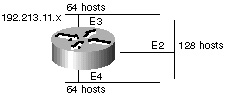
Proper Implementation of VLSM The best way to use VLSM is to keep the existing numbering plan in place and gradually migrate some networks in order to recover address space. In Cisco’s network, the Class B address is 131.108.0.0. You use a mask of 255.255.255.0. You could take one address and decide to use it for all serial lines, for example: Existing addressing: network number: 131.108.0.0, mask: 255.255.255.0 Reserve one existing subnet for all serial lines: network number: 131.108.254.0, mask: 255.255.255.252 The use of VLSM allows 6-bits or 64 subnets for serial lines. These subnets would be 131.108.254.1 and 131.108.254.2 131.108.254.5 and 131.108.254.6 131.108.254.9 and 131.108.254.10 . . . Note that host numbers with all zeros or all ones are not supported. This achieves a 64:1 improvement in address space allocation on serial lines. It also assumes that you are including subnet zero and the broadcast. Inter-Operability Issues with VLSM Routers in a single area must agree on the network mask. IGRP does not support VLSM. So when information is redistributed from OSPF to IGRP, only a single mask will be used. The best way to make this work is to hide all VLSMs from IGRP. OSPF should summarize the networks to achieve one mask per network number. The idea behind VLSMs is to offer more flexibility in dealing with dividing a major network into multiple subnets and still being able to maintain an adequate number of hosts in each subnet. Without VLSM, one subnet mask can only be applied to a major network. This would restrict the number of hosts given the number of subnets required. If you pick the mask such that you have enough subnets, you wouldn’t be able to allocate enough hosts in each subnet. The same is true for the hosts: a mask that allows enough hosts might not provide enough subnet space. For example, suppose you were assigned a Class C network 192.214.11.0, and you need to divide that network into three subnets with 100 hosts in one subnet and 50 hosts for each of the remaining subnets. Ignoring the two end limits 0 and 255, you theoretically have available to you 256 addresses (192.214.11.0-192.214.11.255). This cannot be done without VLSM. Figure 5-19 shows an example of how you can use VLSM to segment a Class C address.
There are a handful of subnet masks that can be used; remember that a mask should have a contiguous number of ones starting from the left and the rest of the bits being all zeros. As an example, some common VLSM configurations include the following:
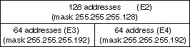
Without VLSM, you have the choice of using mask 255.255.255.128 and dividing the addresses into two subnets with 128 hosts each or using 255.255.255.192 and dividing the space into four subnets with 64 hosts each. This would not meet the requirement. By using multiple masks you can use mask 128 and further subnet the second chunk of addresses with mask 192. Figure 5-20 shows the proper division of address space.
Now, be careful in allocating the IP addresses to each mask. After you assign an IP address to the router or to a host, you have used up the whole subnet for that segment. For example, if you assign 192.214.11.10 255.255.255.128 to E2, the whole range of addresses between 192.214.11.0 and 192.214.11.127 is consumed by E2. In the same way if you assign 192.214.11.160 255.255.255.128 to E2, the whole range of addresses between 192.214.11.128 and 192.214.11.255 is consumed by the E2 segment.
| ||||||||||||||||||||||||||||||||||||||
EAN: 2147483647
Pages: 200