Networking Routing Fundamentals
Internetwork ComponentsThis section discusses some of the actual physical components that make use of the theories previously discussed: OSI model, IP addresses, subnet masks, routing, and so forth. There will be a bit more theory as the basic assumptions or common definitions many people have for the following terms and conditions are discussed. These definitions are based upon Cisco’s Internetworking Terms and Acronyms. In some cases, their definitions have been expanded to help readers of all knowledge levels better understand and grasp their place in a network. NetworksA network is defined as a collection of computers, printers, routers, switches, and other devices that are able to communicate with each other over some transmission medium, such as Frame Relay, ISDN, or ATM. BridgesA bridge is a device that connects and passes packets between two network segments that use the same communications protocol. Bridges operate at the Data Link layer (Layer 2) of the OSI reference model. In general, a bridge will filter, forward, or flood an incoming frame based on the MAC address of that frame. GatewaysIn the IP community, a gateway was an older term used to refer to a routing device. Today, the term router is used to describe nodes that perform this function, and gateway refers to a special-purpose device that performs an Application layer conversion of information from one protocol stack to another. HubsHubs are devices that contain multiple independent, but connected, modules of network and internetwork equipment. Hubs can be active (where they repeat signals sent through them) or passive (where they do not repeat, but merely split, signals sent through them). SwitchesSwitch is the general term applied to an electronic or mechanical device that enables a connection to be established as necessary and terminated when there is no longer a session to support. Switches are network devices that filter, forward, and flood frames based on the destination address of each frame. The switch operates at the Data Link layer of the OSI model. LAN SwitchesLAN switches are high-speed switches that forward packets between data-link segments. Most LAN switches forward traffic based on MAC addresses. This variety of LAN switch is sometimes called a frame switch. LAN switches are often categorized according to the method they use to forward traffic: cut-through packet switching or store-and-forward packet switching. Multilayer switches are an intelligent subset of LAN switches.
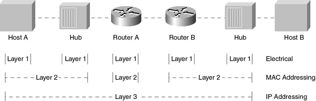
Packet SwitchesPacket switches are WAN devices that route packets along the most efficient path and enable a communications channel to be shared by multiple connections. Sometimes a packet switch is referred to as a packet switch node (PSN). CSUA channel service unit (CSU) is a digital interface device that connects end-user equipment to the local digital telephone loop. Often referred to with DSU as CSU/DSU. See also DSU. DSUA data service unit (DSU) is a device used in digital transmission that adapts the physical interface on a DTE device to a transmission facility such as T1 or E1. The DSU is also responsible for functions such as signal timing. Often referred to with CSU as CSU/DSU. See also CSU. RouterA router is a network layer device that uses one or more metrics to determine the optimal path along which network traffic should be forwarded. Routers forward packets from one network to another based on network layer information. They are occasionally called gateways (although this definition of gateway is becoming increasingly outdated). Compare with gateway. RoutingRouting is the process of finding a path to a destination host. Routing is very complex in large networks because of the many potential intermediate destinations a packet might traverse before reaching its destination host. Component Interaction with the OSI ModelThe only layers of the OSI model you are concerned with are Layers 1, 2, and 3. Layer 1 (Physical layer) is the hardware layer that deals strictly with the electrical interfaces between devices, the format of the bit stream, and so forth. Layer 2 (Data Link layer) interfaces between the hardware and the software and provides error correction. From a TCP/IP view, the Data Link layer is made up of the MAC (Media Access Control) layer. Layer 3 (Network layer) and below are responsible for the establishment, maintenance, and termination of connections. For purposes here, these are the only layers you are concerned with when discussing how the various network components interact with the OSI model. The other upper layers are only concerned with the payload that needs to be delivered. To put it another way, Layer 1 is the electrical interface, and Layer 2 is the layer in which software of the device talks to the next device on the LAN or WAN (not the hub which really is part of Layer 1). Layer 2 is also where bridges work. To a bridge, everything above Layer 2 is its payload, and it doesn’t care about anything else—it just provides bridging to everything above Layer 2. Layer 3 is the Network layer. In this example, it is where routing of setting up sessions and connections occurs. However, this is not done by the routing protocol, which is independent of all this. The routing protocol really is more like an application whose data is used in the actual routing process. The examples that follow assume a lot of things (protocol-wise) have already occurred with which the reader need not be concerned for the purposes of this discussion. Let’s look at a connection end to end: The scenario is Host A on LAN A wants to talk to Host B on LAN B.
As you can see from Figure 2-10, the layers terminate in different places. The Layer 1 parts are not very important; you need only to note that they are there.
|
EAN: 2147483647
Pages: 200