7.1 Introduction to Interfaces
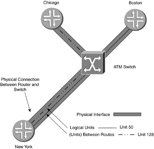
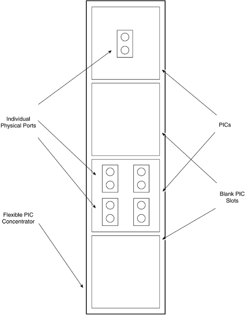
| The interfaces on a router are used to communicate with other connected network devices. Interfaces come in many different types and speeds. Interfaces for Juniper Networks routers can be electrical or optical, and they can range in speed from thousands to tens of billions of bits per second, depending on the need. A router uses interfaces to connect to physically external devices. In addition, a router has some interfaces that are internal virtual interfaces to assist the Internet processor. These interfaces are created in router memory and cannot be physically touched. Juniper Networks routers support a diverse set of physical interfaces, or ports, that can accommodate the needs of most ISPs and large-enterprise networks. The range in available bandwidths of interfaces for a Juniper Networks router is currently DS-0 (DS-3 with channels down to the 64Kbps level) to OC-192 (10Gbps). In addition to the wide range of bandwidths offered , Juniper Networks offers a variety of different types of interfaces. POS, ATM, Fast Ethernet, and GigE are just some of the different interfaces Juniper Networks offers for its routers. Physical interfaces technically also include the console interface because it enables communications from outside the router. The list of available interfaces grows constantly as technology is enhanced and bandwidth requirements increase. Internal virtual router interfaces are created in memory and in the processes of the routing engine. Virtual interfaces serve a variety of purposes, including acting as points for forwarding data in a manner similar to physical interfaces. One very important virtual interface is the loopback interface. The loopback interface can be used for giving a router a stable IP address for identity. Other virtual interfaces can include generic route encapsulation (GRE) and IP-IP tunnel interfaces. These types of interfaces are internal to the Internet processor and are used to set up virtual connections to other routers with tunnel interfaces for data forwarding. Some virtual interfaces, such as the GRE and IP-IP tunnel interfaces, require specialized hardware to implement. 7.1.1 Logical UnitsThe discussion on ATM in Section 2.2.2.9 discussed how some technologies have the ability to create many logical interfaces that are assigned as part of one physical interface. This feature allows many different networks to be configured on one physical port. These logical interfaces are called logical units. Each of the logical units on a port, or physical interface, has features that can be configured independently of the other logical units. In addition, there are some global features that are configured on the physical interface that affect all the logical units at once. Juniper Networks assigns these logical unit properties to a physical port. By creating different units, different properties can be assigned to each unit. Logical units are known as subinterfaces with other vendors . For example, in Figure 7-1, each of the three routers has a physical connection to an ATM switch. Router New York has two configured logical units, one for each virtual circuit. One logical unit's data is switched via VPI/VCI to Chicago and the other to Boston. Since these logical units are configured for different IP subnets, router New York has two network connections on one physical interface. Any data destined for router Chicago from New York will leave New York from unit 128 with a different VPI/VCI pair than unit 50, which would forward data towards router Boston. This logical use of units in JUNOS provides you with a way to group different units that belong to a physical interface logically. Figure 7-1. Physical and Logical Interfaces The physical port on router New York must be properly configured to communicate with the switch; otherwise , the logical units will not be able to communicate properly with the other routers. Once the physical communication is working, then the logical interfaces can be configured. In practice, both are configured at the same time or one at a time, but the important thing to remember is that the logical unit is dependent on the physical interface. 7.1.2 Interface Naming and NumberingJuniper Networks interface cards are called PICs and house the actual physical interface ports. PICs are carried on FPCs. A PIC can contain only the one type of port, but different types of PICs can be installed in an FPC as explained in Chapter 3. In Figure 7-2, an FPC is illustrated with two different PICs installed and two blank PIC slots. The FPC is the carrier card that houses the PICs. Each PIC is made up of physical interfaces. For example, a one-port OC-12 ATM PIC could be installed in the same FPC as a four-port OC-3 POS PIC. Figure 7-2. PICs in an FPC Juniper Networks currently has two routers that have the FPCs inserted into slots vertically and one router that has the FPCs inserted horizontally. The FPCs in the M40 and M160 are inserted vertically and the M20 has the FPCs inserted horizontally. The M5 and M10 do not use a removable FPC slot; the PICs can be inserted and removed individually, but the slots are called FEBs. For the M20, M40, and M160, PICs are inserted first into the FPC; then, the full FPC is inserted into the appropriate slot on the router. Since different types of PICs have different configuration parameters and characteristics, a way of differentiating between the types of PICs must be used. To identify which type of PIC is being configured, Juniper Networks uses JUNOS software designation codes listed in Table 7-1. Table 7-1. Interface Types and JUNOS Software Designations
Because there can be multiple FPCs, PICs, interfaces, and logical units (identified as units), each type is represented a little differently in JUNOS for interface identification. For example: " type " -x/y/z.a In this format
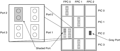
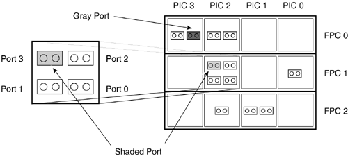
An example of a full interface name would be at-3/3/0.75 . This represents an ATM interface, in FPC slot 3, in PIC 3, port 0, logical unit 75. The unit number is an arbitrary number from 0 to 16,384. Some interface encapsulations only support unit 0 (e.g., POS interfaces running PPP), while others support multiple units (e.g., ATM interfaces). When in configuration mode, you can use the show command to see the output for the logical interface configuration, which is separated by unit, as is shown below. The unit 75, has one set of parameters while unit 105 has another. The parameters in this case are the different VCI assignments and the different IP network address, as we can see in the following code output: [edit interfaces at-3/3/0] lab@Boston# show atm-options { vpi 0 maximum-vcs 150; } unit 75 { point-to-point; vci 75; family inet { address 192.168.75.1/30; } } unit 105 { vci 105; family inet { address 192.168.105.1/30; } } [edit interfaces at-3/3/0] lab@Boston# When referring to a specific logical unit or showing interface statistics and its respective status, the decimal notation is used. The command show interfaces (interfaces) can be used to show and observe information about the link status and characteristics of the specified interface, as is shown in the following command output. Notice that the main physical interface is shown, and then the logical units associated with it are displayed. lab@Boston> show interfaces at-3/3/0 Physical interface: at-3/3/0, Enabled, Physical link is Up Interface index: 24, SNMP ifIndex: 48 Link-level type: ATM-PVC, MTU: 4482, Clocking: Internal, SONET mode, Speed: OC3, Loopback: None, Payload scrambler: Enabled Device flags : Present Running Link flags : None Input rate : 0 bps (0 pps) Output rate : 0 bps (0 pps) SONET alarms : None SONET defects : None Logical interface at-3/3/0.75 (Index 4) (SNMP ifIndex 50) Flags: Point-To-Point SNMP-Traps Encapsulation: ATM-SNAP Input packets : 0 Output packets: 0 Protocol inet, MTU: 4470, Flags: None Addresses, Flags: Is-Preferred Is-Primary Destination: 192.168.75.0/30, Local: 192.168.75.1 VCI 0.75 Flags: Active Total down time: 0 sec, Last down: Never Traffic statistics: Input packets: 0 Output packets: 0 Logical interface at-3/3/0.105 (Index 5) (SNMP ifIndex 51) Flags: Point-To-Point SNMP-Traps Encapsulation: ATM-SNAP Input packets : 0 Output packets: 0 Protocol inet, MTU: 4470, Flags: None Addresses, Flags: Is-Preferred Is-Primary Destination: 192.168.105.0/30, Local: 192.168.105.1 VCI 0.105 Flags: Active Total down time: 0 sec, Last down: Never Traffic statistics: Input packets: 0 Output packets: 0 lab@Boston> To find out which physical PICs are installed in the router, the show chassis hardware command can be used. As shown here, when the command is run on router Boston, the various PICs installed in FPCs 0, 2, and 3 are shown below each FPC entry: [edit] lab@Boston# run show chassis hardware Hardware inventory: Item Version Part number Serial number Description Chassis 20797 m40 Backplane REV 02 710-001348 AB6859 Power supply A REV 04 740-000234 000963 AC Power supply B REV 04 740-000234 000961 AC Maxicab REV 07 710-000229 AF8436 Minicab REV 03 710-000482 AE9763 Display REV 08 710-000150 AE9963 Host Present SCB REV 02 710-001838 AF7654 Internet Processor II FPC 0 REV 10 710-000175 AA4830 PIC 0 REV 06 750-000616 AA6736 1x OC-12 ATM, MM PIC 1 REV 06 750-000616 AA5469 1x OC-12 ATM, MM PIC 2 REV 07 750-002303 AK8035 4x F/E, 100 BASE-TX FPC 2 REV 01 710-001292 AH4745 PIC 0 REV 02 750-001020 AD4661 1x OC-12 SONET, MM PIC 1 REV 02 750-000618 AB1174 4x T3 PIC 2 REV 03 750-000611 AC0856 4x OC-3 SONET, MM FPC 3 REV 09 710-000175 AA6064 PIC 3 REV 03 750-000612 AA1774 2x OC-3 ATM, MM Looking at the output, you can now differentiate the name assignments of the FPCs, PICs, interfaces, and logical units. 7.1.3 Position NumberingThe position and numbering of an FPC and a PIC can be a bit confusing and needs some explanation. The numbering changes not only on the position the card holds in the router, but it also depends on the router that you are using, as we will explain in the next section. 7.1.3.1 FPC and PIC Numbering for the M40 and M160For the M40 and M160, the vertical FPC slots are numbered from left to right, 0 to 7 (the SCB slot on the M40 is not counted). PICs in the FPCs are counted top to bottom. Four standard PICs can fit into an FPC, so they are numbered 0 to 3. Lastly the ports are numbered, starting upper right in the PIC, and are counted down, moving from the upper left down. In Figure 7-3, FPCs are installed with various PICs in an M40. Using the FPC/PIC/port format, the gray port is assigned 2/2/0. The shaded port is assigned 0/2/2. Figure 7-3. M40 Interface Assignment If there are only two ports in a PIC, the assignment number starts at 0 for the top port and the bottom will be 1. If there is only one interface port on a PIC, then the port assignment is 0. 7.1.3.2 FPC and PIC Numbering for the M5, M10, and M20The M5, M10, and M20 routers have much smaller chassis than the M40 and M160. The FPC slots are inserted horizontally to ensure proper airflow. The FPC slots are numbered top to bottom; the PICs are numbered right to left. The ports are numbered left to right, bottom to top starting at the bottom right and moving left. All Juniper Networks router-numbering schemes begin with 0. Figure 7-4 illustrates the interface assignment for the horizontal chassis of the M20. The gray port is assigned the number 0/3/0 and the shaded port is assigned the number 1/2/3. Figure 7-4. M20 Interface Assignment With the M5 only having one FPC slot, the assignment for that slot is 0. Although it seems somewhat complicated to remember, the M5/10/20 port numbering scheme is the same as that for the M40/M160 with your head tilted to the left. 7.1.4 Interface Configuration BasicsConfiguration commands for router interfaces in JUNOS software are located in the [edit interfaces (interface) ] command hierarchy of the command-line interface, where (interface) represents the interface you wish to configure. Both the physical ports and logical units are configured from this hierarchy level. As you can see below, the configurable transient physical interfaces, which already have some elements configured on router New York are shown. In addition, loopback0 ( lo0 ) and the management fxp0 are listed. [edit interfaces] lab@newyork# set ? Possible completions: <interface_name> Interface name + apply-groups Groups from which to inherit configuration data at-0/1/0 at-0/1/1 fe-0/0/0 fe-0/0/1 fe-0/0/3 fxp0 ge-0/2/0 ge-0/3/0 lo0 so-0/3/0 > traceoptions Interface trace options [edit interfaces] lab@newyork# To configure a logical unit, the hierarchy for the physical interface that will carry that logical unit must be entered. To edit the ATM interface for port 0/1/1 or to configure logical units on 0/1/1, the set commands must be entered. For this example, the prompt was moved to the directories where the commands were located to show the possible command completions. [edit interfaces] lab@newyork# edit at-0/1/1 [edit interfaces at-0/1/1] lab@newyork# set ? Possible completions: accounting-profile Accounting profile name + apply-groups Groups from which to inherit configuration data > atm-options ATM interface-specific options clocking Interface clock source description Text description of interface disable Disable this interface > e3-options E3 interface-specific options encapsulation Physical link-layer encapsulation > hold-time Hold time for link up and link down mtu Maximum transmit packet size (256..9192) no-traps Don't enable SNMP notifications on state changes > sonet-options SONET interface-specific options > t3-options T3 interface-specific options > traceoptions Interface trace options traps Enable SNMP notifications on state changes > unit Logical interface [edit interfaces at-0/1/1] lab@newyork# Changes made to the configuration of a physical interface will affect both the interface and all logical units created on it. For example, if you use the set disable command on the physical interface, no logical units on the physical interface will be able to communicate. 7.1.4.1 Logical Units ConfigurationLogical units are noted by the number after the period in the naming scheme. For example, a logical unit designated at-0/1/1.100 would be logical unit 100 of the ATM interface in 0/1/1. The range of possible logical unit numbers from 0 to 16,384 is shown below: [edit interfaces at-0/1/1] lab@newyork# set unit ? Possible completions: <interface_unit_number> Logical unit number (0..16384) [edit interfaces at-0/1/1] lab@newyork# set unit 380 It is common practice to try to associate the logical unit number with something about the network for which that the logical unit will be configured. For instance, if an ATM logical unit were to be configured on a PVC with a VPI/VCI of 3:80, the unit number could be configured as 380 for that particular logical unit. This can assist with troubleshooting or statistics gathering. Once the logical unit is assigned a unit number, all of the logical network parameters for that logical unit can be configured. Some of the parameters that can be configured on a logical unit are protocol family address assignment, the DLCI or VPI/VCI assignments for NBMA PVCs, and packet filtering. If no unit configuration is required, such as when using a Fast Ethernet port to connect a single network, a unit still has to be defined. In this instance, unit 0 must be used. 7.1.4.2 Network AddressingAlthough there are several types of protocol families and addresses that can be assigned to a logical unit, the discussion in this chapter will discuss IP network addressing (known as family inet ). The other family addresses, such as MPLS and ISO, will be discussed in their respective protocol chapters. The IP protocol family is assigned to a unit using the command inet , and then an IP address can be assigned under that family as shown below: [edit interfaces fe-0/0/3 unit 0] lab@newyork# set family ? Possible completions: + apply-groups Groups from which to inherit configuration data > inet Internet protocol (IPv4) parameters > iso OSI ISO protocol parameters > mpls MPLS protocol parameters [edit interfaces fe-0/0/3 unit 0] lab@newyork# set family Once you are in the unit hierarchy of the logical unit, the command to add an IP address is set family inet address (address/mask) , as is demonstrated next: [edit interfaces fe-0/0/3 unit 0] lab@newyork# set family inet address 192.168.50.5/24 [edit interfaces fe-0/0/3 unit 0] lab@newyork# show family inet { address 192.168.50.5/24; } [edit interfaces fe-0/0/3 unit 0] lab@newyork# The main thing to remember is that the protocol family has to be assigned on a logical unit to enable the protocol on that logical unit. |
EAN: 2147483647
Pages: 176


